Principles of Path Detection
You can configure the path detection function on the device that functions as the ingress or egress node on a VXLAN network through the CLI or NMS and enable the inbound interface of the device to construct and forward a 5-tuple packet based on packet sending parameters. Each path detection-capable device along the path is configured with a specific DSCP value so that it can obtain the packet information and send the packet information as well as the inbound and outbound interface information to the controller. The controller then displays the path information of the specified 5-tuple flow based on the information sent by the devices.
Path Detection
IPv4 Path Detection
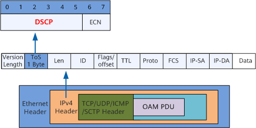
An IPv4 path detection packet is a common IPv4 TCP/UDP/ICMP/SCTP packet, as shown in Figure 1. The device identifies a path detection packet based on the detection flag (DSCP) and detection data (OAM PDU).
IPv6 Path Detection
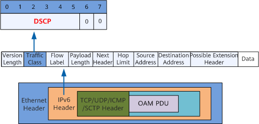
An IPv6 path detection packet is a common IPv6 TCP/UDP/ICMP/SCTP packet, as shown in Figure 2. The device identifies a path detection packet based on the detection flag (DSCP value) and detection data (OAM PDU).

- DSCP-based IPv4/IPv6 path detection can detect the traffic path between any two devices only in VXLAN tunnel scenarios.
- Plan the DSCP value used for identifying path detection packets before configuring DSCP-based IPv4/IPv6 path detection and ensure that the DSCP value is not used by any other service flow.
- If the path detection packet is a UDP packet with either the source or destination port number being 2152, the packet must contain a GTP header.
Path Detection Process
In Figure 3, the controller has established NETCONF connections with devices at the DC-GW, spine, and leaf layers. Devices at the DG-GW layer are VXLAN Layer 3 gateways, devices at the spine layer are transparent transmission devices on the VXLAN network, and devices at the leaf layer are VXLAN Layer 2 gateways. The path from Device1 to VM1 needs to be detected. Assuming the detected path is Device1->Device2->Device3->VM1, the path detection process is as follows:
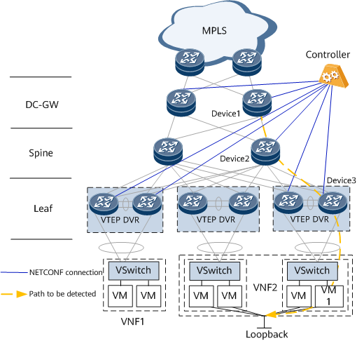
- Enable DSCP-based path detection on all devices along the path to be detected.
- Deliver a packet sending command on the ingress node Device1 through the CLI or NMS to construct and forward a packet.
- In the upstream direction, Device 1 directly obtains the packet and inbound interface information and sends the information to the controller.
- In the downstream direction, Device 1 identifies and parses the packet and sends the packet and outbound interface information to the controller.
- Device 2 identifies the detection packet and sends the packet information as well as the inbound and outbound interface information to the controller.
- Device 3 identifies the detection packet and sends the packet information as well as the inbound and outbound interface information to the controller.
- The controller displays information about the path from the DC-GW ingress to the leaf egress.
On the live network, the NetEngine 8000 F is generally deployed at the DG-GW layer.