FlexE Mux
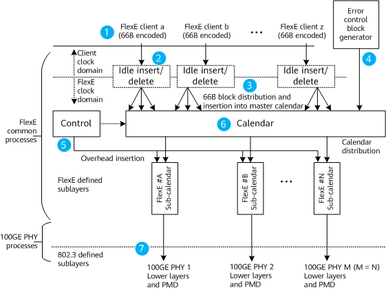
The FlexE mux function defined in the FlexE standards refers to the FlexE shim function in the transmit direction of an interface. That is, the FlexE client is mapped to the FlexE group in the transmit direction. As shown in Figure 1, a FlexE group consisting of 100GE PHYs is used as an example to describe the working process of FlexE mux.
- Each FlexE client is presented to the FlexE shim as a 64B/66B encoded bit stream.
- A FlexE client is rate-adapted in idle insertion/deletion mode to match the clock of the FlexE group. The rate of the adapted signal is slightly less than the nominal rate of the FlexE client to allow room for the alignment markers on the PHYs of the FlexE group and insertion of the FlexE overhead.
- The 66B blocks from each FlexE client are sequentially distributed and inserted into the calendar.
- Error control blocks are generated for insertion into unused or unavailable timeslots to ensure that the data in these timeslots is not considered valid.
- The control function manages which timeslots each FlexE client is inserted into and inserts the FlexE overhead on each PHY in the transmit direction.
- Calendar distribution is responsible for allocating the 66B blocks of different FlexE clients in the calendar to a sub-calendar according to the TDM timeslot distribution mechanism. The sub-calendar then schedules the 66B blocks to the corresponding PHYs in the FlexE group in polling mode.
- The stream of 66B blocks of each PHY is distributed to the PCS lanes of that PHY with the insertion of alignment markers, and the layers below the PCS continues to be used intact as specified for the standard Ethernet defined by IEEE 802.3.