Status Control
VRRP
VRRP is a fault-tolerant protocol defined in relevant standards . As shown in Figure 1, the routers on the LAN (Device1, Device2, and Device3) are arranged in a backup group using VRRP. This backup group functions as a virtual router.
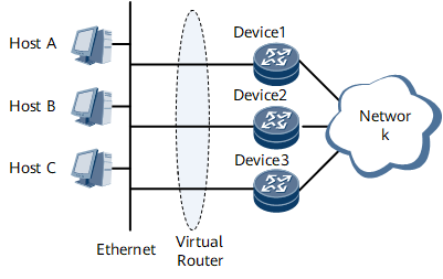
On the LAN, hosts need to obtain only the IP address of the virtual router rather than the IP address of each router in the backup group. The hosts set the IP address of the virtual router as the address of their default gateway. Then, the hosts can communicate with an external network through the virtual gateway.
VRRP dynamically associates the virtual router with a physical router that transmits services. When the physical router fails, another router is selected to take over services and user services are not affected. The internal network and the external network can communicate without interruption.
Principles of the Active/Standby Switchover
During the implementation of high reliability of services, VRRP is responsible for the negotiation of the master and standby devices; BFD or Eth OAM is responsible for fast detection of link faults to perform a rapid active/standby switchover.
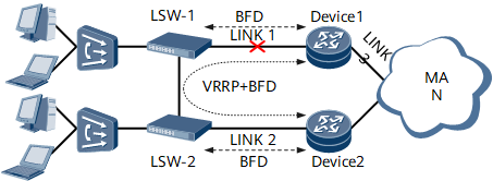
As shown in Figure 2, the two routers negotiate the master and standby states using VRRP. The NetEngine 8000 F supports active/standby status selection of interfaces and sub-interfaces.
BFD is enabled between the two routers to detect links between the two devices. BFD in this mode is called Peer-BFD. BFD is also enabled between the router and the LSW to detect links between the router and the LSW. BFD in this mode is called Link-BFD.
When a link fails, through VRRP, the new master and standby devices can be negotiated, but several seconds are needed and the requirements of carrier-grade services cannot be met. Through BFD or Eth OAM, a faulty link can be detected in several milliseconds and the device can perform a fast active/standby switchover with the help of VRRP.
During the implementation of an active/standby switchover, VRRP has to determine device status based on Link-BFD status and Peer-BFD status. As shown in Figure 2, when Link 1 fails, the Peer-BFD status and Link-BFD status of Device1 both go down and Device1 becomes the standby device. In this case, the Peer-BFD status of Device2 goes down but the Link-BFD status of Device2 is still up. Therefore, Device2 becomes the master device.
In actual networking, certain LSWs may not support BFD. In this case, you have to select another detection mechanism. Besides BFD, the NetEngine 8000 F also supports detection of links connecting to LSWs through Eth OAM.
The NetEngine 8000 F supports monitoring of upstream links (for example, Link 3 in Figure 2) to enhance reliability protection for the network side. When an upstream link fails, the NetEngine 8000 F responds to the link failure quickly and performs an active/standby link switchover.
Principles of the Active/Standby Switchover in an E-Trunk Access Scenario
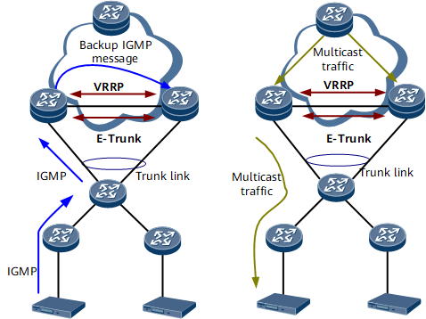
On the network shown in Figure 3, E-Trunk, an extension to LACP, implements link aggregation among BRASs. E-Trunk controls the active and standby states of bundled member links between two BRASs and an aggregation switch. E-Trunk allows the active link to forward data packets and does not allow the standby link to forward or receive data packets.
VRRP is enabled on directly connected interfaces on the master and slave BRASs, and VRRP tracks Eth-Trunk interfaces. The VRRP status is consistent with the E-Trunk status.
The master NetEngine 8000 F receives an IGMP Report or Leave message from an STB, and backs up the message to the slave NetEngine 8000 F. After receiving the IGMP Report or Leave message, the slave NetEngine 8000 F pulls multicast traffic, establishes a multicast forwarding entry, and prunes a multicast path.