NAT Traffic Diversion
After user packets arrive at a NAT device, the device does not perform NAT directly for the user packet. The device diverts packets matching specified ACL rules to a NAT service board for processing. This implementation is called NAT traffic diversion. NAT traffic diversion is performed in either inbound-interface or outbound-interface mode.
Inbound-Interface Traffic Diversion
In the inbound-interface traffic diversion mode, a traffic policy is applied to an inbound interface to divert packets. A traffic classifier in the traffic policy defines ACL rules used to match against packets, and a traffic behavior defines the NAT processing for packets.
After the traffic policy is applied to the inbound interface, NAT translation is performed for packets matching the ACL rules defined in the traffic policy. The packets that do not match the traffic policy are forwarded based on the regular process.
In the carrier scenario, NAT is required for all user traffic. The inbound-interface traffic diversion mode is recommended.
- Forwarding process in inbound-interface traffic diversion mode (forward traffic)Figure 1 Forwarding process in inbound-interface traffic diversion mode (forward traffic)
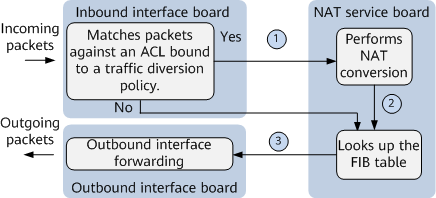
As shown in the preceding figure, the forward traffic forwarding process in inbound-interface traffic diversion mode is as follows:
- After user packets on the private network reach a device, the device matches the 5-tuple information in the user packets against the ACL rules defined in a traffic policy bound to an interface.
- If a match is found, the packets are diverted to a NAT board for processing.
- If the packets do not match any ACL rule, the packets are forwarded according to the regular process.
- The NAT service board allocates a public IP address and port number to each user packet based on 5-tuple information carried in the user packet, and translates the private IP address and port number in the user packet into the public IP address and port number, respectively.
- The NAT board searches the FIB table for a specified outbound interface and forwards the converted packets to a next hop through the outbound interface.
- After user packets on the private network reach a device, the device matches the 5-tuple information in the user packets against the ACL rules defined in a traffic policy bound to an interface.
- Forwarding process in inbound-interface traffic diversion mode (reverse traffic)Figure 2 Forwarding process in inbound-interface traffic diversion mode (reverse traffic)
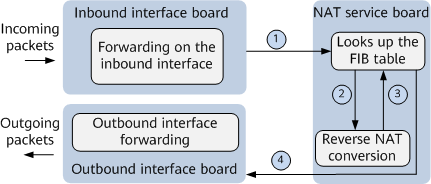 As shown in the preceding figure, the reverse traffic forwarding process in inbound-interface traffic diversion mode is as follows:
- User packets on the public network side are forwarded to the NAT service board through the inbound interface board.
- The NAT service board searches the FIB table for an outbound interface.
- If FIB entries hit NAT address pool routes, the device forwards the packets to the NAT service board for processing.
- If FIB entries hit non-NAT address pool routes, the device forwards the packets based on the regular forwarding process.
- The NAT service board replaces the destination address and port number of each user packet with the corresponding private address and port number based on the reverse NAT mapping.
- The NAT service board searches for the outbound interface based on the post-translated destination private IP addresses and sends each post-translated packet to the private network through the selected outbound interface.
Outbound-Interface Traffic Diversion
In outbound-interface traffic diversion mode, the NetEngine 8000 F diverts traffic based on the ACL rules bound to a NAT instance. The NetEngine 8000 F filters out user packets. The packets destined for the internal network are forwarded based on the regular forwarding process. Packets destined for the public network are diverted to the NAT service board for processing.
In the enterprise network scenario, there is a large amount of internal communication traffic, and NAT does not need to be performed. NAT is performed only for the traffic that needs to access the external network. In such a scenario, the outbound-interface traffic diversion solution is recommended.
- Forwarding process in outbound-interface traffic diversion mode (forward traffic)Figure 3 Forwarding process in outbound-interface traffic diversion mode (forward traffic)
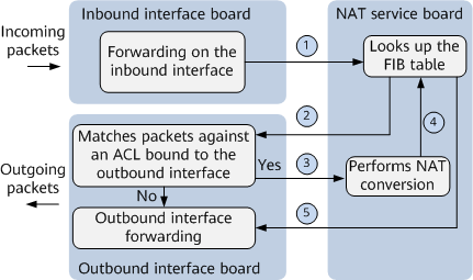
As shown in the preceding figure, the forward traffic forwarding process in outbound-interface traffic diversion mode is as follows:
- User packets on the private network side are forwarded to the NAT service board through the inbound interface board.
- The NAT service board searches the FIB table for an outbound interface based on destination addresses of the packets. After obtaining the outbound interface information, the NAT service board forwards the packets to the outbound interface board.
- On the outbound interface board, the device uses the route's outbound interface information and the 5-tuple information in the user packets to match against ACL rules applied to the outbound interface.
- If the packets match an ACL rule, the packets are diverted to the NAT service board for address translation.
- If the packets do not match any ACL rule, the packets are directly sent to the next hop through a specified interface.
- The NAT service board replaces the private IP address and port number in each of the user packets with the allocated public IP address and port number.
- The NAT service board re-searches the FIB table for the outbound interface information based on the destination address (the ACL rules on the outbound interface are no longer matched) and sends the packets to the next hop through the selected outbound interface.
- Forwarding process in outbound-interface traffic diversion mode (reverse traffic)
The forwarding process is the same as the reverse traffic forwarding process in inbound-interface traffic diversion mode. For details, see Forwarding process in inbound-interface traffic diversion mode (reverse traffic).