NAT ALG
The application level gateway (ALG) function provides transparent translation for certain application layer protocols.
Many application layer protocol packets contain user information, including IP addresses and port numbers. These protocol packets may fail to be forwarded because NAT cannot identify the IP addresses and port numbers carried in these protocol packets. To address this problem, the NAT ALG technique can be used to translate IP addresses and port numbers carried in application-layer protocol information, as well as IP addresses and port numbers in packets.
NAT ALG supports various protocols, such as the Internet Control Message Protocol (ICMP), UDP-based Session Initiation Protocol (SIP), TCP-based Real-Time Streaming Protocol (RTSP), Point-to-Point Tunneling Protocol (PPTP), UDP-based domain name service (DNS) mapping, and File Transfer Protocol (FTP).
NAT ALG for FTP
- An FTP server on a public network is working in port mode.
- An FTP server on a private network is working in passive (PASV) mode.

- The private network host and the public network FTP server establish a TCP control connection using three-way handshakes.
- The host sends an FTP Port packet carrying a destination IP address and a port number to the FTP server to request to establish a data connection.
- Upon receipt of the FTP Port packet, the ALG-capable NAT device maps the private IP address and port number carried in the payload to the public IP address and port number. In this example, the private IP address 192.168.0.10 carried in the payload is translated into a public IP address 1.1.1.1, and private port 1024 into public port 5000.
- Upon receipt of the FTP Port packet, the public network FTP server parses the packet and sends a packet with a destination public IP address of 1.1.1.1 and a port number of 5000 to initiate a data connection to the private network host.
- Upon receipt of the packet, the NAT device translates the destination public IP address and port number to the private IP address and port number, respectively, before sending the packet to the host. Then the host can successfully establish a data connection to the FTP server.
NAT ALG for FTPS-to-FTP Switching
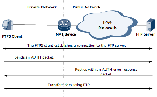
FTPS is an encryption protocol that adds transport layer security (TLS) and secure socket layer (SSL) information to FTP. As shown in Figure 2, when an FTPS client sends an AUTH packet to an FTP server, the FTPS client receives an error response packet from the FTP server. The NAT device allows the FTPS AUTH and its response packets to pass through without discarding them. After receiving the error response packet, the FTPS client automatically switches to the FTP mode and continues to exchange data with the FTP server using the FTP ALG function. This ensures that the basic FTP functions are available and services are not affected.
NAT ALG for ICMP

The data payload of the ICMP error message carries a private IP address. Without the NAT ALG function, the NAT device forwards the message to the public network host without processing the private IP address in the data payload. Upon receipt of the message, the public network host cannot identify the application to which the message belongs. In addition, the private IP address of the private network FTP server is leaked to the public network.
With the NAT ALG function, the NAT device translates the private IP address 192.168.0.10 of the FTP server to a public IP address 1.1.1.1 and then forwards the ICMP message to the public network host. Upon receipt of the ICMP message, the host can properly identify the FTP application. In addition, the risk of leaking the private IP address of the FTP server to the public network is eliminated.
NAT ALG for RTSP

- Inband mode: Also called the interleaving mode. A media stream is transmitted along a control channel and does not need to be processed by the ALG function.
- Outband mode: A media stream is transmitted along a data channel and carries a port number that is negotiated using control packets. The ALG function must process the media stream packets.
- The client is on a private network, and the server is on a public network. The client's private port number in the payload of each Setup request packet is replaced with a public port number. The client's public port number in each Setup response packet is replaced with the client's private port number.
- The client is on the public network, and the server is on the private network. The client's private network port in the payload of the Setup request packet does not need to be replaced. The public port number of the server in the payload of the Setup response packet must be replaced with the public port number.
The ALG module also identifies an RTSP Teardown request, changes the aging time of the flow table, and deletes the flow table to release resources.
NAT ALG for PPTP
In Figure 5, a PPTP client is on a private network, and a PPTP server is on a public network. Packets transmitted along the data channel between the client and server must be processed by the ALG function. Generic Routing Encapsulation (GRE) packets transmitted along the data channel carry IP addresses and call IDs, but not port numbers. If a NAT device maps IP addresses in packets of various PPTP clients to the same public IP address, the NAT device cannot determine to which clients the returned public network PPTP packets should be sent.
To distinguish between multiple clients on the private network side, the call ID of the client needs to be replaced when the data packet passes through the NAT device, and the mapping needs to be stored. In this way, when a packet is sent to the server, even if multiple clients use the same call ID, the call IDs are replaced with different call IDs after NAT, so that the server can distinguish between the packets. In addition, the NAT device can identify the packets returned by the server, and replace the call IDs with the original ones.

- The PPTP client and server establish a PPTP TCP connection.
- The PPTP client sends a PPTP Outgoing-Call-Request packet to the PPTP server to establish a PPTP tunnel and selects a call ID to identify the PPTP tunnel along which the client sends data to the PPTP server.
- Upon receipt of the Outgoing-Call-Request packet, the PPTP server sends an Outgoing-Call-Reply packet and selects a call ID to identify the tunnel along which the server sends data to the client.
- The PPTP client and server send GRE data packets on a GRE tunnel.
- The client sends a PPTP Clear-Call-Request packet to inform the PPTP server that the PPTP control connection is to be terminated.
- The server replies with a PPTP Call-Disconnected-Notify packet.
- The server replies with a PPTP Stop-Control-Connection-Reply packet.
- The client closes the PPTP TCP connection.
NAT ALG for SIP
ALG for SIP when users are attached to different NAT devices
As shown in Figure 6, all user addresses are private addresses and the users are connected to different NAT devices. NAT device 1 performs the ALG processing on the SIP packet of UA1, and the UAS delivers a media stream channel to UA1. NAT device 2 performs the ALG processing on the SIP packet of UA2, and the UAS delivers a media stream channel to UA2. UA1 and UA2 communicate with each other through the media stream channels.ALG for SIP when users are attached to the same NAT device
As shown in Figure 7, all user addresses are private addresses and the users are connected to the same NAT device. When the SIP packet of UA1 is processed by the ALG function on the NAT device, and the UAS delivers a media stream channel to UA1. The NAT device finds that the destination address is included in an address pool and therefore uses the ALG function to process the destination information. Subsequently, UA1 and UA2 communicate with each other through the media stream channel.ALG for SIP when users are on private and public networks
As shown in Figure 8, UA1 is a private network user, and UA2 is a public network user. In the direction from UA1 to UA2, the ALG function processes source information. In the direction from UA2 to UA1, the ALG function processes destination information.


NAT ALG for UDP-based DNS Mapping
- A DNS server is on a private network, and an ISP server is on either a public or private network. In this situation, DNS ALG is not used.
- A DNS server and an ISP server are on a public network. This situation is supported natively and does not require NAT devices.
- A DNS server is deployed on a public network, and an ISP server is on a private network. The NAT internal server function or DNS mapping function can be used.
The NAT internal server function can handle the NAT traversal issue for DNS packets, but the disadvantage is that subsequent traffic must be forwarded by the NAT device. Therefore, the customer's devices must support DNS mapping. When DNS Answer packets traverse the NAT device, the public IP address in the payload is replaced with a private IP address, so that a user can access the internal ISP server using the private IP address.

- A private network host sends a DNS Query packet carrying a domain name to a public network DNS server.
- Upon receipt of the packet, the DNS server obtains the public IP address (1.1.1.1) mapped to the domain name of www.huawei.com, adds the IP address to the DNS Answer packet, and sends the response to the public IP address corresponding to the private network host.
- Upon receipt of the response, the NAT ALG-enabled device replaces the public IP address 1.1.1.1 in the payload of the DNS Answer packet with the private IP address 192.168.0.10 assigned to the WWW server on the private network. The NAT ALG-enabled device then forwards the DNS Answer packet to the private network host.
- Upon receipt of the DNS Answer packet, the host obtains the private IP address mapped to the domain name of www.huawei.com and is able to communicate with the WWW server.