Example for Configuring Local Flow Mirroring
This section provides an example for configuring local flow mirroring.
Networking Requirements
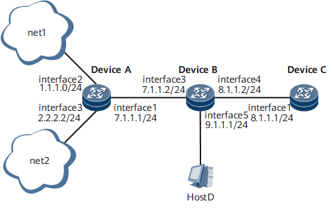
As shown in Figure 1, interface5 on DeviceB is configured as the observing port to monitor the packets from DeviceA to DeviceB through interface 3. Then, flow mirroring is configured on interface 3.
A traffic policy is configured on interface 3 of DeviceB to improve the operation efficiency of Host D. In this manner, only the packets whose source address is 2.2.2.2 are copied to interface5.

- The configurations in this example are performed on Device A, Device B, and Device C. HUAWEI NetEngine 8000 F Series can function as Device A, Device B, and Device C.
Interfaces 1 through 5 in this example represent GE 0/1/0, GE 0/1/8, GE 0/1/1, GE 0/1/2, and GE 0/1/3, respectively.
Device Name |
Interface Name |
Interface IP Address |
Interface MAC Address |
|---|---|---|---|
DeviceA |
GE0/1/0 |
7.1.1.1/24 |
- |
DeviceA |
GE0/1/8 |
1.1.1.0/24 |
- |
DeviceA |
GE0/1/1 |
2.2.2.2/24 |
- |
DeviceB |
GE0/1/1 |
7.1.1.2/24 |
- |
DeviceB |
GE0/1/2 |
8.1.1.2/24 |
- |
DeviceB |
GE0/1/3 |
9.1.1.1/24 |
- |
DeviceC |
GE0/1/0 |
8.1.1.1/24 |
- |
Configuration Roadmap
The configuration roadmap is as follows:
Configure GE 0/1/3 on DeviceB as the observing port.
Configure the traffic policy on GE 0/1/1 of DeviceB and specify the traffic behavior in the traffic policy as mirroring enabled.
Data Preparation
To complete the configuration, you need the following data:
IP addresses of interfaces
Types and numbers of the observing port and mirroring port
ACL number, traffic classification name, traffic behavior name, and traffic policy name
Procedure
- Configure the IP addresses of the interfaces on the routers and ensure that the route between the routers is reachable. The configuration details are not mentioned here.
- Configure GE 0/1/3 as an observing port.
<routerB> system-view
[~routerB] interface gigabitethernet0/1/3
[~routerB-GigabitEthernet0/1/3] port-observing observe-index 3
[*routerB-GigabitEthernet0/1/3] commit
- Configure the traffic policy on GE 0/1/1, the mirroring port.
# Define ACL rules.
[~routerB] acl 2001
[*routerB-acl-basic-2001] rule permit source 2.2.2.2 0.0.0.0
[*routerB-acl-basic-2001] commit
[~routerB-acl-basic-2001] quit
# Configure traffic classifiers and create matching rules based on ACL numbers.
[~routerB] traffic classifier a
[*routerB-classifier-a] if-match acl 2001
[*routerB-classifier-a] commit
[~routerB-classifier-a] quit
# After the configuration, run the display traffic classifier user-defined command to view the configuration of the traffic classifiers.
[~routerB] display traffic classifier user-defined
User Defined Classifier Information:
   Classifier: a
    Operator: OR
    Rule(s) : if-match acl 2001 precedence 2
# Define the traffic behavior and enable flow mirroring.
[~routerB] traffic behavior e
[*routerB-behavior-e] port-mirroring enable
[*routerB-behavior-e] port-mirroring to observe-index 3
[*routerB-behavior-e] commit
[~routerB-behavior-e] quit
# Define traffic policies and associate traffic classes with traffic behaviors.
[~routerB] traffic policy 1
[*routerB-trafficpolicy-1] classifier a behavior e
[*routerB-trafficpolicy-1] commit
[~routerB-trafficpolicy-1] quit
# Apply the traffic policy to the interface.
[~routerB] interface gigabitethernet0/1/1
[~routerB-GigabitEthernet0/1/1] traffic-policy 1 inbound
[*routerB-GigabitEthernet0/1/1] commit
[~routerB-GigabitEthernet0/1/1] quit
- Verify the configuration.
You can run the ping command to view the status of traffic mirroring. Alternatively, you can use another manner to generate traffic to view the status of mirroring. For example, DeviceA sends 10 ping packets whose source address is 2.2.2.2/32 and 10 ping packets whose source address is 1.1.1.0/32 to GE 0/1/1. Host D can receive the 10 packets whose source address is 2.2.2.2/32 but cannot receive the 10 packets whose source address is 1.1.1.0/32.
Configuration Files
Device A configuration file
#
 sysname routerA
#
interface GigabitEthernet0/1/0
 undo shutdown
 ip address 7.1.1.1 255.255.255.0
#
interface GigabitEthernet0/1/8
 undo shutdown
 ip address 1.1.1.1 255.255.255.0
#
interface GigabitEthernet0/1/1
 undo shutdown
 ip address 2.2.2.2 255.255.255.0
#
return
Device B configuration file
#
 sysname routerB
#
acl number 2001
 rule 5 permit source 2.2.2.2 0
#
traffic classifier a operator or
 if-match acl 2001
#
traffic behavior e
 port-mirroring enable
 port-mirroring to observe-index 3
#
traffic policy 1
 classifier a behavior e
#
interface GigabitEthernet0/1/1
 undo shutdown
 ip address 7.1.1.2 255.255.255.0
 traffic-policy 1 inbound
#
interface GigabitEthernet0/1/2
 undo shutdown
 ip address 8.1.1.2 255.255.255.0
#
interface GigabitEthernet0/1/3
 undo shutdown
 port-observing observe-index 3
#
return
Device C configuration file
#
 sysname routerC
#
interface GigabitEthernet0/1/0
 undo shutdown
 ip address 8.1.1.1 255.255.255.0
#
return