Example for Connecting a BRAS User to the Internet Through a VLL
Networking Requirements
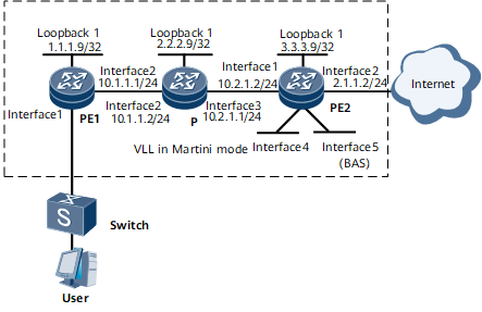
On the network shown in Figure 1, PE1, P, and PE2 form a VLL in LDP mode. The router functions as PE2, which is the BRAS. The BRAS user connects to the Internet through the VLL. Two virtual interfaces VE 0/1/32 and VE 0/1/33 are created on the router. VE 0/1/32 terminates the VLL service, and VE 0/1/33.1 functions as a BAS interface to authenticate the user. The requirements are as follows:
The user belongs to the domain isp1 and connects to the Internet through VE 0/1/33.1 in PPPoEoVoQ mode.
The user obtains an IP address from the address pool pool1. The address segment in the address pool is 172.30.1.2-172.30.1.200.
RADIUS authentication and RADIUS accounting are used. The RADIUS server address is 192.168.7.249, and the authentication and accounting port numbers are 1812 and 1813, respectively. RADIUS+1.1 is used, with the key of Huawei.
The DNS server address is 192.168.7.252.
The accounting and authentication schemes are acct1 and auth1, respectively.

Configuration Roadmap
The configuration roadmap is as follows:
Configure the VE interface for terminating the VLL service and the VE interface for accessing the Internet on the router. Bind the two VE interfaces to a VE-group.
Configure the VLL.
Enable VLL access.
Configure BRAS access on PE2, with VE 0/1/33.1 functioning as a BAS interface.
Data Preparation
To complete the configuration, you need the following data:
VE-group number
MPLS LSR IDs on the PE and P routers: IP addresses of the corresponding loopback 1 interfaces
Configuration Procedure
Create two VE interfaces on PE2 and bind them to a VE-group.
# Create VE 0/1/32 for terminating the VLL service.
<HUAWEI> system-view
[~HUAWEI] sysname PE2
[*PE2] commit
[~PE2] interface virtual-ethernet0/1/32
[*PE2-Virtual-Ethernet0/1/32] ve-group 1 l2-terminate
[*PE2-Virtual-Ethernet0/1/32] quit
[*PE2] commit
# Create VE 0/1/33 for accessing the Internet.
[~PE2] interface virtual-ethernet0/1/33
[*PE2-Virtual-Ethernet0/1/33] ve-group 1 l3-access
[*PE2-Virtual-Ethernet0/1/33] quit
[*PE2] commit
Configure the VLL.
# Configure an IGP (for example, OSPF) on the VLL backbone.
When configuring OSPF, advertise the 32-bit IP addresses of the loopback interfaces on the PEs and the P.
For configuration details, see Configuration Files in this section.
# Configure basic MPLS functions and LDP on the MPLS backbone.
Configure PE1.
<HUAWEI> system-view
[~HUAWEI] sysname PE1
[*PE1] commit
[~PE1] mpls lsr-id 1.1.1.9
[*PE1] mpls
[*PE1-mpls] quit
[*PE1] mpls ldp
[*PE1-mpls-ldp] quit
[*PE1] commit
[~PE1] interface gigabitethernet0/1/0
[*PE1-GigabitEthernet0/1/0] mpls
[*PE1-GigabitEthernet0/1/0] mpls ldp
[*PE1-GigabitEthernet0/1/0] undo shutdown
[*PE1-GigabitEthernet0/1/0] quit
[*PE1] commit
[~PE1] quit
Configure the P.
<HUAWEI> system-view
[~HUAWEI] sysname P
[*P] commit
[~P] mpls lsr-id 2.2.2.9
[*P] mpls
[*P-mpls] quit
[*P] commit
[~P] mpls ldp
[*P-mpls-ldp] quit
[*P] commit
[~P] interface gigabitethernet0/1/0
[*P-GigabitEthernet0/1/0] mpls
[*P-GigabitEthernet0/1/0] mpls ldp
[*P-GigabitEthernet0/1/0] undo shutdown
[*P-GigabitEthernet0/1/0] quit
[*P] commit
[~P] interface gigabitethernet0/1/8
[*P-GigabitEthernet0/1/8] mpls
[*P-GigabitEthernet0/1/8] mpls ldp
[*P-GigabitEthernet0/1/8] undo shutdown
[*P-GigabitEthernet0/1/8] quit
[*P] commit
[~P] quit
Configure PE2.
[~PE2] mpls lsr-id 3.3.3.9
[*PE2] mpls
[*PE2-mpls] quit
[*PE2] commit
[~PE2] mpls ldp
[*PE2-mpls-ldp] quit
[*PE2] commit
[~PE2] interface gigabitethernet0/1/32
[*PE2-GigabitEthernet0/1/32] mpls
[*PE2-GigabitEthernet0/1/32] mpls ldp
[*PE2-GigabitEthernet0/1/32] undo shutdown
[*PE2-GigabitEthernet0/1/32] quit
[*PE2] commit
[~PE2] quit
# Set up a remote LDP session between the PEs.
Configure PE1.
[~PE1] mpls ldp remote-peer PE2
[*PE1-mpls-ldp-remote-1] remote-ip 3.3.3.9
[*PE1-mpls-ldp-remote-1] quit
[*PE1] commit
[~PE1] quit
Configure PE2.
[~PE2] mpls ldp remote-peer PE1
[*PE2-mpls-ldp-remote-1] remote-ip 1.1.1.9
[*PE2-mpls-ldp-remote-1] quit
[*PE2] commit
[~PE2] quit
# Enable VLL on the PEs and create static VCs.
Create an L2VC on PE1's GE 0/1/32.1.
[~PE1] mpls l2vpn
[*PE1-l2vpn] quit
[*PE1] commit
[~PE1] interface gigabitethernet 0/1/32.1
[*PE1-GigabitEthernet0/1/32.1] vlan-type dot1q 1
[*PE1-GigabitEthernet0/1/32.1] mpls l2vc 3.3.3.9 101
[*PE1-GigabitEthernet0/1/32.1] undo shutdown
[*PE1-GigabitEthernet0/1/32.1] quit
[*PE1] commit
[~PE1] quit
Create an L2VC on PE2's VE 0/1/32.1.
[~PE2] mpls l2vpn
[*PE2-l2vpn] quit
[*PE2] commit
[~PE2] interface virtual-ethernet0/1/32.1
[*PE2-Virtual-Ethernet0/1/32.1] vlan-type dot1q 1
[*PE2-Virtual-Ethernet0/1/32.1] mpls l2vc 1.1.1.9 101
[*PE2-Virtual-Ethernet0/1/32.1] quit
[*PE2] commit
[~PE2] quit
# Verify the configuration.
Check the L2VPN connection information on the PEs. The command output on each PE shows that an L2VC has been set up and its status is up.
The following example uses the command output on PE2.
[~PE2] display mpls l2vc
  Total ldp vc : 1     1 up       0 down
 *Client Interface     : Virtual-Ethernet0/1/32
  Session State        : up
  AC Status            : up
  VC State             : up
  VC ID                : 101
  VC Type              : ethernet
  Destination          : 1.1.1.9
  Local VC Label       : 1025
  Remote VC Label      : 1024
  Control Word         : Disable
  Local VC MTU         : 1500
  Romete VC MTU        : 1500
  Tunnel Policy Name   : --
  Traffic Behavior Name: --
  PW Template Name     : --
  Create time          : 0 days, 0 hours, 3 minutes, 14 seconds
  UP time              : 0 days, 0 hours, 1 minutes, 48 seconds
  Last change time     : 0 days, 0 hours, 1 minutes, 48 seconds
Configure BRAS access on PE2, with VE 0/1/33.1 functioning as a BAS interface.
# Configure a VT.
[~PE2] interface virtual-template 1
[*PE2-Virtual-Template1] ppp authentication-mode chap
[*PE2-Virtual-Template1] quit
[*PE2] commit
# Configure an authentication scheme.
[~PE2] aaa
[*PE2-aaa] authentication-scheme auth1
[*PE2-aaa-authen-auth1] authentication-mode radius
[*PE2-aaa-authen-auth1] quit
[*PE2] commit
# Configure an accounting scheme.
[~PE2-aaa] accounting-scheme acct1
[*PE2-aaa-accounting-acct1] accounting-mode radius
[*PE2-aaa-accounting-acct1] quit
[*PE2-aaa] quit
[*PE2] commit
# Configure a RADIUS server group.
[~PE2] radius-server group rd1
[*PE2-radius-rd1] radius-server authentication 192.168.7.249 1812
[*PE2-radius-rd1] radius-server accounting 192.168.7.249 1813
[*PE2-radius-rd1] radius-server type plus11
[*PE2-radius-rd1] radius-server shared-key-cipher Huawei
[*PE2-radius-rd1] quit
[*PE2] commit
# Configure a local address pool.
[~PE2] ip pool pool1 bas local
[*PE2-ip-pool-pool1] gateway 172.30.1.1 255.255.255.0
[*PE2-ip-pool-pool1] commit
[~PE2-ip-pool-pool1] section 0 172.30.1.2 172.30.1.200
[~PE2-ip-pool-pool1] dns-server 192.168.7.252
[*PE2-ip-pool-pool1] commit
[~PE2-ip-pool-pool1] quit
# Configure a domain named isp1.
[~PE2] aaa
[*PE2-aaa] domain isp1
[*PE2-aaa-domain-isp1] authentication-scheme auth1
[*PE2-aaa-domain-isp1] accounting-scheme acct1
[*PE2-aaa-domain-isp1] radius-server group rd1
[*PE2-aaa-domain-isp1] ip-pool pool1
[*PE2-aaa-domain-isp1] quit
[*PE2] commit
# Bind the VT to VE 5/0/1.
[~PE2] interface virtual-ethernet0/1/33.1
[*PE2-Virtual-Ethernet0/1/33.1] pppoe-server bind virtual-template 1
[*PE2-Virtual-Ethernet0/1/33.1] quit
[*PE2] commit
# Configure VE 0/1/33.1 as a BAS interface.
[~PE2] interface virtual-ethernet0/1/33.1
[*PE2-Virtual-Ethernet0/1/33.1] user-vlan 1 2 qinq 1
[*PE2-Virtual-Ethernet0/1/33.1.1-vlan-1-2-QinQ-100] quit
[*PE2-Virtual-Ethernet0/1/33.1] commit
[~PE2-Virtual-Ethernet0/1/33.1] bas
[~PE2-Virtual-Ethernet0/1/33.1-bas] access-type layer2-subscriber
[*PE2-Virtual-Ethernet0/1/33.1-bas] authentication-method ppp
[*PE2-Virtual-Ethernet0/1/33.1-bas] commit
[~PE2-Virtual-Ethernet0/1/33.1-bas] quit
[~PE2-Virtual-Ethernet0/1/33.1] quit
# Configure GE 0/1/0.
[~PE2] interface GigabitEthernet 0/1/0
[*PE2-GigabitEthernet0/1/0] ip address 10.1.1.2 255.255.255.0
[*PE2-GigabitEthernet0/1/0] undo shutdown
[*PE2-GigabitEthernet0/1/0] quit
[*PE2] commit
Configuration Files
PE1 configuration file
#
 sysname PE1
#
 mpls lsr-id 1.1.1.9
 mpls
#
 mpls l2vpn
#
mpls ldp
#
interface GigabitEthernet0/1/0
 undo shutdown
 ip address 10.1.1.1 255.255.255.0
 mpls
 mpls ldp
#
 mpls ldp remote-peer PE2
 remote-ip 3.3.3.9
#
interface GigabitEthernet0/1/32.1
 vlan-type dot1q 1
 mpls l2vc 3.3.3.9 101
#
interface LoopBack1
 ip address 1.1.1.9 255.255.255.255
#
ospf 1
 area 0.0.0.0
  network 10.1.1.0 0.0.0.255
  network 1.1.1.9 0.0.0.0
#
return
P configuration file
#
 sysname P
#
 mpls lsr-id 2.2.2.9
 mpls
#
mpls ldp
#
interface GigabitEthernet0/1/0
 undo shutdown
 ip address 10.1.1.2 255.255.255.0
 mpls
 mpls ldp
#
interface GigabitEthernet0/1/8
 undo shutdown
 ip address 10.2.1.1 255.255.255.0
 mpls
 mpls ldp
#
interface LoopBack1
 ip address 2.2.2.9 255.255.255.255
#
ospf 1
 area 0.0.0.0
  network 10.1.1.0 0.0.0.255
  network 10.2.1.0 0.0.0.255
  network 2.2.2.9 0.0.0.0
#
return
PE2 configuration file
#
 sysname PE2
#
radius-server group rd1
 radius-server authentication 192.168.7.249 1645 weight 0
 radius-server accounting 192.168.7.249 1646 weight 0
 radius-server shared-key-cipher %^%#`E)v.Q@BHVzxxZ;ij{>&_M0!TGP7YRA@8a7mq<\/%^%#
 radius-server type plus11
#
mpls lsr-id 3.3.3.9
 mpls
#
 mpls l2vpn
#
mpls ldp
#
 mpls ldp remote-peer pe1
  remote-ip 1.1.1.9
#
interface Virtual-Template1
 ppp authentication-mode chap
#
interface GigabitEthernet0/1/0
 undo shutdown
 ip address 10.1.1.2 255.255.255.0
#
interface GigabitEthernet0/1/32
 undo shutdown
 ip address 10.2.1.2 255.255.255.0
 mpls
 mpls ldp
#
interface Virtual-Ethernet0/1/32
 undo shutdown
 ve-group 1 l2-terminate
#
interface Virtual-Ethernet0/1/32.1
 vlan-type dot1q 1
 mpls l2vc 1.1.1.9 101
#
interface Virtual-Ethernet0/1/33
 undo shutdown
 ve-group 1 l3-access
#
interface Virtual-Ethernet0/1/33.1
 undo shutdown
 pppoe-server bind virtual-template 1
 user-vlan 1 2 qinq 1
 bas
  access-type layer2-subscriber
#
interface LoopBack1
 ip address 3.3.3.9 255.255.255.255
#
ip pool pool1 bas local
 gateway 172.30.1.1 255.255.255.0
 section 0 172.30.1.2 172.30.1.200
 dns-server 192.168.7.252
#
aaa
authentication-scheme auth1
 authentication-mode radius
accounting-scheme acct1
 accounting-mode radius
 domain isp1
  authentication-scheme auth1
  accounting-scheme acct1
  radius-server group rd1
  ip-pool pool1
#
ospf 1
 area 0.0.0.0
  network 10.2.1.0 0.0.0.255
  network 3.3.3.9 0.0.0.0
#
return