Example for Configuring PPPoEv6 User Access in a 6VPE Scenario
This section provides an example for configuring PPPoEv6 user access in a 6VPE scenario. The BRAS uses RADIUS authentication and accounting to implement user access.
Networking Requirements
After an IPv6 user terminal initiates a PPPoE connection request, PE1 that functions as a BRAS authenticates the IPv6 user. After the IPv6 user is authenticated, if the IPv6 user wants to communicate with other user sites over a public network without making the internal route information known to the public network, BGP/MPLS IPv6 VPN can be configured. BGP/MPLS IPv6 VPN can isolate VPN services from each other by allowing intra-VPN access and prohibiting inter-VPN access.
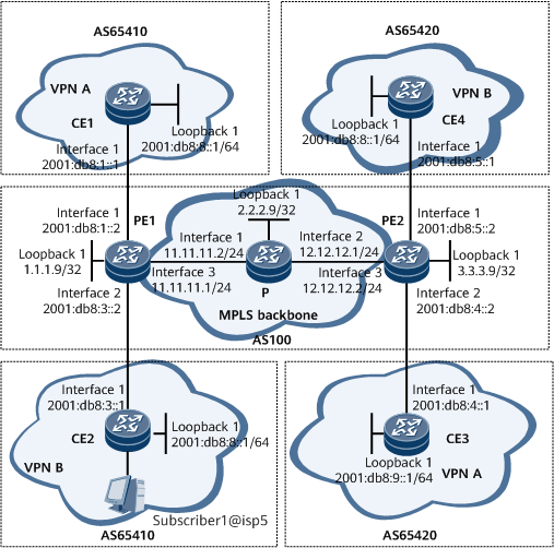
On the network shown in Figure 1, CE1 and CE3 belong to VPN A, and CE2 and CE4 belong to VPN B. It is required that BGP/MPLS IPv6 VPN be configured to allow the sites in VPN A and VPN B to communicate with each other through an MPLS backbone network instead of directly communicating with each other. In addition, PEs and CEs are required to exchange routes in different ways.

Configuration Roadmap
The configuration roadmap is as follows:
- Assign an IPv4 address or an IPv6 address to each device interface.
Configure an IGP on the IPv4 backbone network to implement PE interworking.
Configure MPLS and MPLS LDP on each PE and the P and establish an LDP LSP between PEs.
- Configure a VPN instance that supports the IPv6 address family on both PE1 and PE2, and bind the VPN instances to the interfaces connecting PEs to CEs.
- Establish a VPNv6 peer relationship between PEs.
Configure BGP4+ between PE1 and CE1 and between PE2 and CE4.
Configure static routes between PE1 and CE2.
Configure OSPFv3 between PE2 and CE3.
- Configure BRAS access on PE1.
Data Preparation
To complete the configuration, you need the following data:
AS numbers of PEs and CEs
VPN instance names
Attributes of the VPN instance that supports the IPv6 address family, such as the RD and VPN target
VT number
Authentication and accounting schemes and their names
RADIUS server group name and RADIUS server addresses
Start ID and end ID of a VLAN range created on a BAS interface
Local prefix pool name
Assignable IPv6 prefixes and prefix lengths
Local address pool name
Domain name
Configuration Procedure
Assign an IPv4 address or an IPv6 address to each device interface. For configuration details, see Configuration Files in this section.
- Configure an IGP on the IPv4 backbone network to implement communication between PEs. In this example, IS-IS is used as an IGP.
# Configure PE1.
[~PE1] isis 1
[*PE1-isis-1] network-entity 10.1111.1111.1111.00
[*PE1-isis-1] quit
[*PE1] interface gigabitEthernet 0/1/16
[*PE1-GigabitEthernet0/1/16] isis enable 1
[*PE1-GigabitEthernet0/1/16] quit
[*PE1] interface loopback 1
[*PE1-LoopBack1] isis enable 1
[*PE1-LoopBack1] quit
[*PE1] commit
Repeat this step for the P and PE2. For configuration details, see Configuration Files in this section.
After the configuration is complete, PE1, PE2, and the P can learn routes, including the routes to loopback interfaces, from one another. You can run the display ip routing-table command to view the routes. The following example uses the command output on PE1.
[~PE1] display ip routing-table
Route Flags: R - relay, D - download to fib, T - to vpn-instance, B - black hole route
------------------------------------------------------------------------------
Routing Table: _public_
         Destinations : 11        Routes : 11

Destination/Mask    Proto    Pre    Cost      Flags     NextHop         Interface

        1.1.1.9/32  Direct   0       0          D     127.0.0.1        InLoopBack0
        2.2.2.9/32  ISIS-L2  15      10         D     11.11.11.2       GigabitEthernet0/1/16
        3.3.3.9/32  ISIS-L2  15      20         D     11.11.11.2       GigabitEthernet0/1/16
      127.0.0.0/8   Direct   0       0          D     127.0.0.1        InLoopBack0
      127.0.0.1/32  Direct   0       0          D     127.0.0.1        InLoopBack0
127.255.255.255/32  Direct   0       0          D     127.0.0.1        InLoopBack0
    11.11.11.0/24   Direct   0       0          D    11.11.11.1        GigabitEthernet0/1/16
    11.11.11.1/32   Direct   0       0          D     127.0.0.1        GigabitEthernet0/1/16
  11.11.11.255/32   Direct   0       0          D     127.0.0.1        GigabitEthernet0/1/16
    12.12.12.0/24   ISIS-L2  15      20         D    11.11.11.2        GigabitEthernet0/1/16
255.255.255.255/32  Direct   0       0          D     127.0.0.1        InLoopBack0
- Enable MPLS and MPLS LDP on each device on the IPv4 backbone network and establish an LDP LSP between PE1 and PE2.
# Enable MPLS and MPLS LDP on PE1.
[~PE1] mpls lsr-id 1.1.1.9
[*PE1] mpls
[*PE1-mpls] quit
[*PE1] mpls ldp
[*PE1-mpls-ldp] quit
[*PE1] interface gigabitEthernet 0/1/16
[*PE1-GigabitEthernet0/1/16] mpls
[*PE1-GigabitEthernet0/1/16] mpls ldp
[*PE1-GigabitEthernet0/1/16] quit
[*PE1] commit
Repeat this step for the P and PE2. For configuration details, see Configuration Files in this section.
After completing the configurations, an LDP LSP can be established between PE1 and PE2. Run the display mpls ldp lsp command. The command output shows LDP LSP configurations. The following example uses the command output on PE1.
[~PE1] display mpls ldp lsp
 LDP LSP Information
 -------------------------------------------------------------------------------
 DestAddress/Mask   In/OutLabel    UpstreamPeer    NextHop         OutInterface
 -------------------------------------------------------------------------------
 1.1.1.9/32         3/NULL         2.2.2.9         127.0.0.1       InLoop0
*1.1.1.9/32         Liberal/1024                   DS/2.2.2.9
 2.2.2.9/32         NULL/3         -               11.11.11.2       GE0/1/16
 2.2.2.9/32         1024/3         2.2.2.9         11.11.11.2       GE0/1/16
 3.3.3.9/32         NULL/1025      -               11.11.11.2       GE0/1/16
 3.3.3.9/32         1025/1025      2.2.2.9         11.11.11.2       GE0/1/16
 -------------------------------------------------------------------------------
 TOTAL: 5 Normal LSP(s) Found.
 TOTAL: 1 Liberal LSP(s) Found.
 TOTAL: 0 Frr LSP(s) Found.
An asterisk (*) before an LSP means the LSP is not established  An asterisk (*) before a Label means the USCB or DSCB is stale  An asterisk (*) before an UpstreamPeer means the session is stale  An asterisk (*) before a DS means the session is stale  An asterisk (*) before a NextHop means the LSP is FRR LSP
- Configure a VPN instance that supports the IPv6 address family on each PE and bind the VPN instance to the interface connecting a PE to the attached CE.
# On PE1, configure an IPv6-address-family-capable VPN instance named vpna.
[~PE1] ip vpn-instance vpna
[*PE1-vpn-instance-vpna] ipv6-family
[*PE1-vpn-instance-vpna-af-ipv6] route-distinguisher 100:1
[*PE1-vpn-instance-vpna-af-ipv6] vpn-target 22:22 export-extcommunity
[*PE1-vpn-instance-vpna-af-ipv6] vpn-target 33:33 import-extcommunity
[*PE1-vpn-instance-vpna-af-ipv6] quit
[*PE1-vpn-instance-vpna] quit
[*PE1] commit
# Bind the VPN instance named vpna to the interface directly connecting PE1 to CE1.
[~PE1] interface gigabitethernet 0/1/0
[*PE1-GigabitEthernet0/1/0] ip binding vpn-instance vpna
[*PE1-GigabitEthernet0/1/0] ipv6 enable
[*PE1-GigabitEthernet0/1/0] ipv6 address 2001:db8:1::2 64
[*PE1-GigabitEthernet0/1/0] quit
[*PE1] commit
# On PE1, configure an IPv6-address-family-capable VPN instance named vpnb.
[~PE1] ip vpn-instance vpnb
[*PE1-vpn-instance-vpnb] ipv6-family
[*PE1-vpn-instance-vpnb-af-ipv6] route-distinguisher 100:3
[*PE1-vpn-instance-vpnb-af-ipv6] vpn-target 44:44 export-extcommunity
[*PE1-vpn-instance-vpnb-af-ipv6] vpn-target 55:55 import-extcommunity
[*PE1-vpn-instance-vpnb-af-ipv6] quit
[*PE1-vpn-instance-vpnb] quit
[*PE1] commit
# Bind the VPN instance named vpnb to the interface directly connecting PE1 to CE2.
[~PE1] interface gigabitethernet 0/1/8
[*PE1-GigabitEthernet0/1/8] ip binding vpn-instance vpnb
[*PE1-GigabitEthernet0/1/8] ipv6 enable
[*PE1-GigabitEthernet0/1/8] ipv6 address 2001:db8:3::2 64
[*PE1-GigabitEthernet0/1/8] quit
[*PE1] commit
Repeat this step for PE2. For configuration details, see Configuration Files in this section.
After the configuration is complete, run the display ip vpn-instance verbose command on each PE to view information about the VPN instances. The command output shows that each PE can ping its connected CE. The following example uses the command output on PE1.
[~PE1] display ip vpn-instance verbose
 Total VPN-Instances configured : 2
 Total IPv4 VPN-Instances configured : 0
 Total IPv6 VPN-Instances configured : 2

 VPN-Instance Name and ID : vpna, 1
  Interfaces : GigabitEthernet0/1/0
 Address family ipv6
  Create date : 2019/07/20 12:31:47
  Up time : 0 days, 04 hours, 37 minutes and 05 seconds
  Vrf Status : UP
  Route Distinguisher : 100:1
  Export VPN Targets :  22:22
  Import VPN Targets :  33:33
  Label Policy : label per route
  Log Interval : 5

 VPN-Instance Name and ID : vpnb, 2
  Interfaces : GigabitEthernet0/1/8
 Address family ipv6
  Create date : 2019/07/20 14:41:46
  Up time : 0 days, 02 hours, 27 minutes and 06 seconds
  Vrf Status : UP
  Route Distinguisher : 100:3
  Export VPN Targets :  44:44
  Import VPN Targets :  55:55
  Label Policy : label per route
  Log Interval : 5
[~PE1] ping ipv6 vpn-instance vpna 2001:db8:1::1
  PING 2001:db8:1::1 : 56  data bytes, press CTRL_C to break
    Reply from 2001:db8:1::1
    bytes=56 Sequence=1 hop limit=64  time = 20 ms
    Reply from 2001:db8:1::1
    bytes=56 Sequence=2 hop limit=64  time = 30 ms
    Reply from 2001:db8:1::1
    bytes=56 Sequence=3 hop limit=64  time = 30 ms
    Reply from 2001:db8:1::1
    bytes=56 Sequence=4 hop limit=64  time = 1 ms
    Reply from 2001:db8:1::1
    bytes=56 Sequence=5 hop limit=64  time = 1 ms

  --- 2001:db8:1::1 ping statistics ---
    5 packet(s) transmitted
    5 packet(s) received
    0.00% packet loss
    round-trip min/avg/max = 1/16/30 ms
- Establish a VPNv6 peer relationship between PEs.
# Configure PE1.
[~PE1] bgp 100
[*PE1-bgp] peer 3.3.3.9 as-number 100
[*PE1-bgp] peer 3.3.3.9 connect-interface loopback 1
[*PE1-bgp] ipv6-family vpnv6
[*PE1-bgp-af-vpnv6] peer 3.3.3.9 enable
[*PE1-bgp-af-vpnv6] quit
[*PE1-bgp] quit
[*PE1] commit
# Configure PE2.
[~PE2] bgp 100
[*PE2-bgp] peer 1.1.1.9 as-number 100
[*PE2-bgp] peer 1.1.1.9 connect-interface loopback 1
[*PE2-bgp] ipv6-family vpnv6
[*PE2-bgp-af-vpnv6] peer 1.1.1.9 enable
[*PE2-bgp-af-vpnv6] quit
[*PE2-bgp] quit
[*PE2] commit
After completing the configurations, run the display bgp vpnv6 all peer command on each PE to view information about the BGP VPNv6 peer relationship. The following example uses the command output on PE1.
[~PE1] display bgp vpnv6 all peer
 BGP local router ID : 1.1.1.9
 Local AS number : 100
 Total number of peers : 1                 Peers in established state : 1

  Peer            V          AS  MsgRcvd  MsgSent  OutQ  Up/Down       State     PrefRcv

  3.3.3.9         4         100        4        3     0 00:01:50   Established    0
The command output shows that State is Established, indicating that the BGP VPNv6 peer relationship between PE1 and PE2 has been established.
- Configure BGP4+ on PE1 and CE1.
# Configure EBGP on PE1.
[~PE1] bgp 100
[*PE1-bgp] ipv6-family vpn-instance vpna
[*PE1-bgp6-vpna] peer 2001:db8:1::1 as-number 65410
[*PE1-bgp6-vpna] quit
[*PE1-bgp] quit
[*PE1] commit
# Configure EBGP on CE1.
[~CE1] bgp 65410
[*CE1-bgp] router-id 10.10.10.10
[*CE1-bgp] peer 2001:db8:1::2 as-number 100
[*CE1-bgp] ipv6-family unicast
[*CE1-bgp-af-ipv6] peer 2001:db8:1::2 enable
[*CE1-bgp-af-ipv6] import-route direct
[*CE1-bgp-af-ipv6] quit
[*CE1-bgp] quit
[*CE1] commit
Repeat this step for PE2 and CE4. For configuration details, see Configuration Files in this section.
After completing the configurations, run the display bgp vpnv6 vpn-instance vpn-instance-name peer command on the PEs to check whether an EBGP peer relationship is established. The following example uses the command output on PE1.
[~PE1] display bgp vpnv6 vpn-instance vpna peer BGP local router ID : 1.1.1.9 Local AS number : 100 Total number of peers : 1 Peers in established state : 1 Peer V AS MsgRcvd MsgSent OutQ Up/Down State PrefRcv 2001:db8:1::1 4 65410 3 3 0 00:00:37 Established 1 - Configure static routes between PE1 and CE2.
# Configure an IPv6 static route for the VPN instance named vpnb on PE1, and import the route into the routing table of the IPv6-address-family-capable BGP VPN instance.
[~PE1] ipv6 route-static vpn-instance vpnb 2001:db8:8:: 64 2001:db8:3::1
[*PE1] bgp 100
[*PE1-bgp] ipv6-family vpn-instance vpnb
[*PE1-bgp6-vpnb] import-route static
[*PE1-bgp6-vpnb] quit
[*PE1-bgp] quit
[*PE1] commit
# Configure an IPv6 default route on CE2.
[~CE2] ipv6 route-static :: 0 2001:db8:3::2
[*CE2] commit
- Configure OSPFv3 between PE2 and CE3.
# Configure OSPFv3 on PE2.
[~PE2] ospfv3 1 vpn-instance vpna
[*PE2-ospfv3-1] router-id 11.11.11.11
[*PE2-ospfv3-1] area 0.0.0.0
[*PE2-ospfv3-1-area 0.0.0.0] quit
[*PE2-ospfv3-1] import-route bgp
[*PE2-ospfv3-1] quit
[*PE2] interface gigabitethernet 0/1/8
[*PE2-Gigabitethernet0/1/8] ospfv3 1 area 0
[*PE2-Gigabitethernet0/1/8] quit
[*PE2] commit
# Import OSPFv3 routes to BGP on PE2.
[~PE2] bgp 100
[*PE2-bgp] ipv6-family vpn-instance vpna
[*PE2-bgp6-vpna] import-route ospfv3 1
[*PE2-bgp6-vpna] quit
[*PE2-bgp] quit
[*PE2] commit
# Configure OSPFv3 on CE3.
[~CE3] ospfv3 1
[*CE3-ospfv3-1] router-id 22.22.22.22
[*CE3-ospfv3-1] area 0.0.0.0
[*CE3-ospfv3-1-area 0.0.0.0] quit
[*CE3-ospfv3-1] quit
[*CE3] interface gigabitethernet 0/1/0
[*CE3-GigabitEthernet0/1/0] ospfv3 1 area 0
[*CE3-GigabitEthernet0/1/0] quit
[*CE3] interface LoopBack 1
[*CE3-LoopBack1] ospfv3 1 area 0
[*CE3-LoopBack1] quit
[*CE3] commit
- Configure PPPoEv6 user access.
- Configure a VPN instance.
<PE1> system-view
[~PE1] ip vpn-instance vpn2
[*PE1-vpn-instance-vpn2] ipv6-family
[*PE1-vpn-instance-vpn2-af-ipv6] route-distinguisher 200:2
[*PE1-vpn-instance-vpn2-af-ipv6] vpn-target 200:2 both
[*PE1-vpn-instance-vpn2-af-ipv6] quit
[*PE1-vpn-instance-vpn2] quit
[*PE1] commit
- Configure a VT.
<PE1> system-view
[~PE1] interface virtual-template 1
[*PE1-Virtual-Template1] ppp authentication-mode chap
[*PE1-Virtual-Template1] quit
[*PE1] commit
Configure AAA schemes.
# Configure an authentication scheme.
[~PE1] aaa
[~PE1-aaa] authentication-scheme auth1
[*PE1-aaa-authen-auth1] authentication-mode radius
[*PE1-aaa-authen-auth1] quit
# Configure an accounting scheme.
[*PE1-aaa] accounting-scheme acct1
[*PE1-aaa-accounting-acct1] accounting-mode radius
[*PE1-aaa-accounting-acct1] quit
[*PE1-aaa] quit
Configure a RADIUS server group.
[~PE1] radius-server group rd1
[*PE1-radius-rd1] radius-server authentication 2001:db8:3::5 1645
[*PE1-radius-rd1] radius-server accounting 2001:db8:3::5 1646
[*PE1-radius-rd1] radius-server type standard
[*PE1-radius-rd1] radius-server shared-key-cipher hello
[*PE1-radius-rd1] quit
- Configure an IPv6 prefix pool.
[~PE1] ipv6 prefix pre1 local
[*PE1-ipv6-prefix-pre1] prefix 2001:db8::/64
[*PE1-ipv6-prefix-pre1] commit
[~PE1-ipv6-prefix-pre1] quit
- Configure an IPv6 address pool and bind the IPv6 prefix pool to the IPv6 address pool.
[~PE1] ipv6 pool pool1 bas local
[*PE1-ipv6-pool-pool1] prefix pre1
[*PE1-ipv6-pool-pool1] dns-server 2001:db8::2:2
[*PE1-ipv6-pool-pool1] commit
[~PE1-ipv6-pool-pool1] quit
- Configure an AAA domain and bind the IPv6 prefix pool to the domain.
[~PE1] aaa
[~PE1-aaa] domain isp1
[*PE1-aaa-domain-isp1] authentication-scheme auth1
[*PE1-aaa-domain-isp1] accounting-scheme acct1
[*PE1-aaa-domain-isp1] radius-server group rd1
[*PE1-aaa-domain-isp1] ipv6-pool pool1
[*PE1-aaa-domain-isp1] vpn-instance vpn2
[*PE1-aaa-domain-isp1] quit
[*PE1-aaa] quit
[*PE1] commit
- Configure interfaces.
# Bind the VT to GE 0/1/8.1.
[~PE1] interface gigabitethernet 0/1/8.1
[*PE1-GigabitEthernet0/1/8.1] pppoe-server bind virtual-template 1
# Configure a BAS interface.
[*PE1-GigabitEthernet0/1/8.1] user-vlan 1 100
[*PE1-GigabitEthernet0/1/8.1-vlan-1-100] commit
[~PE1-GigabitEthernet0/1/8.1-vlan-1-100] quit
[~PE1-GigabitEthernet0/1/8.1] bas
[~PE1-GigabitEthernet0/1/8.1-bas] access-type layer2-subscriber default-domain authentication isp1
[*PE1-GigabitEthernet0/1/8.1-bas] authentication-method-ipv6 ppp
[*PE1-GigabitEthernet0/2/0.1-bas] commit
[~PE1-GigabitEthernet0/1/8.1-bas] quit
# Enable IPv6 on the BAS interface.
[~PE1-GigabitEthernet0/1/8.1] ipv6 enable
[*PE1-GigabitEthernet0/1/8.1] ipv6 address auto link-local
[*PE1-GigabitEthernet0/1/8.1] commit
[~PE1-GigabitEthernet0/1/8.1] quit
- Configure a VPN instance.
- Verify the configuration.
# After completing the configurations, run the display ipv6 prefix pre1 command to view information about the prefix pool named pre1. The command output shows that the prefix pool is a local prefix pool and the prefix address is 2001:db8::/64.
<HUAWEI> display ipv6 prefix pre1
 -------------------------------------------------------------
 Prefix Name        : pre1
 Prefix Index       : 4
 Prefix constant index: -
 Prefix Type        : LOCAL
 Prefix Address     : 2001:db8::
 Prefix Length      : 64
 Reserved Type      : NONE
 Valid Lifetime     : 3 Days 0 Hours 0 Minutes
 Preferred Lifetime : 2 Days 0 Hours 0 Minutes
 IfLocked           : Unlocked
 Vpn instance       : -
 Conflict address   : -
 Free Prefix Count  : 262144
 Used Prefix Count  : 0
 Reserved Prefix Count: 0
 -------------------------------------------------------------
# Run the display ipv6 pool pool1 command to view information about the address pool named pool1. The command output shows that the address pool is a local address pool on the user side and the local prefix pool named pre1 is bound to this address pool.
<HUAWEI> display ipv6 pool pool1
 ----------------------------------------------------------------------
 Pool name          : pool1
 Pool No            : 4
 Pool-constant-index :-
 Pool type          : BAS LOCAL
 Preference         : 0
 Renew time         : 50
 Rebind time        : 80
 Status             : UNLOCKED
 Refresh interval   : 0 Days 0 Hours 0 Minutes
 Used by domain     : 1
 Dhcpv6 Unicast     : disable
 Dhcpv6 rapid-commit: disable
 Dns list           : -
 Dns server master  : 2001:db8::2:2
 Dns server slave   : -
 AFTR name          : -
 ----------------------------------------------------------------------
 Prefix-Name                      Prefix-Type
 ----------------------------------------------------------------------
 pre1                               LOCAL
----------------------------------------------------------------------
# Run the display domain isp1 command to view information about the domain named isp1. The command output shows that the IPv6 address pool named pool1 is bound to this domain.
<~PE1> display domain isp1
------------------------------------------------------------------------------
Domain-name                     : isp1
Domain-state                    : Active
Authentication-scheme-name      : auth1
Accounting-scheme-name          : acct1
Authorization-scheme-name       :
Primary-DNS-IP-address          : -
Second-DNS-IP-address           : -
Web-server-URL-parameter        : No
Slave Web-IP-address            : -
Slave Web-URL                   : -
Slave Web-auth-server           : -
Slave Web-auth-state            : -
Portal-server-URL-parameter     : No
Primary-NBNS-IP-address         : -
Second-NBNS-IP-address          : -
User-group-name                 : -
Idle-data-attribute (time,flow) : 0, 60   I
nstall-BOD-Count                : 0
Report-VSM-User-Count           : 0
Value-added-service             : default
User-access-limit               : 279552
Online-number                   : 0
Web-IP-address                  : -
Web-URL                         : -
Portal-server-IP                : -
Portal-URL                      : -
Portal-force-times              : 2
PPPoE-user-URL                  : Disable
RADIUS-server-template          : rd1
Two-acct-template               : -
HWTACACS-server-template        : -
Bill Flow                       : Disable
Tunnel-acct-2867                : Disabled
Flow Statistic:
Flow-Statistic-Up               : Yes
Flow-Statistic-Down             : Yes
Source-IP-route                 : Disable
IP-warning-threshold            : -
IPv6-warning-threshold          : -
Multicast Forwarding            : Yes
Multicast Virtual               : No
Max-multilist num               : 4
Multicast-profile               : -
Multicast-profile ipv6          : -
IPv6-Pool-name                  : pool1
Quota-out                       : Offline
Service-type                    : -
User-basic-service-ip-type      : -/-/-
PPP-ipv6-address-protocol       : Ndra
IPv6-information-protocol       : Stateless dhcpv6
IPv6-PPP-assign-interfaceid     : Disable
Trigger-packet-wait-delay       : 60s
Peer-backup                     : enable
------------------------------------------------------------------------------
Configuration Files
# PE1 configuration file
#
 sysname PE1
#
ip vpn-instance vpna
 ipv6-family
  route-distinguisher 100:1
  apply-label per-instance
  vpn-target 22:22 export-extcommunity
  vpn-target 33:33 import-extcommunity
#
ip vpn-instance vpnb
 ipv6-family
  route-distinguisher 100:3
  apply-label per-instance
  vpn-target 44:44 export-extcommunity
  vpn-target 55:55 import-extcommunity
#
mpls lsr-id 1.1.1.9
#
mpls
#
mpls ldp
#
isis 1
 network-entity 10.1111.1111.1111.00
#
interface GigabitEthernet0/1/0
 undo shutdown
 ip binding vpn-instance vpna
 ipv6 enable
 ipv6 address 2001:db8:1::2/64
#
interface GigabitEthernet0/1/8
 undo shutdown
 ip binding vpn-instance vpnb
 ipv6 enable
 ipv6 address 2001:db8:3::2/64
#
interface GigabitEthernet0/1/16
 undo shutdown
 ip address 11.11.11.1 255.255.255.0
 isis enable 1
 mpls
 mpls ldp
#
interface LoopBack1
 ip address 1.1.1.9 255.255.255.255
 isis enable 1
#
bgp 100
 peer 3.3.3.9 as-number 100
 peer 3.3.3.9 connect-interface LoopBack1
 #
 ipv4-family unicast
  undo synchronization
  peer 3.3.3.9 enable
 #
 ipv6-family unicast
  undo synchronization
 #
 ipv6-family vpnv6
  policy vpn-target
  peer 3.3.3.9 enable
 #
 ipv6-family vpn-instance vpna
  peer 2001:db8:1::1 as-number 65410
 #
 ipv6-family vpn-instance vpnb
  import-route static
#
 ipv6 route-static vpn-instance vpnb 2001:db8:8:: 64 2001:db8:3::1
#
radius-server group rd1
 radius-server authentication 2001:db8:3::5 1645 weight 0
 radius-server accounting 2001:db8:3::5 1646 weight 0
 radius-server shared-key-cipher %^%#vS%796FO7%C~pB%CR=q;j}gSCqR-X6+P!.DYI@)%^%
#
interface Virtual-Template1
 ppp authentication-mode chap
#
ipv6 prefix pre1 local
prefix 2001:db8::/64
#
ip pool pool1 bas local
prefix pre1
dns-server 2001:db8::2:2
#
aaa
 authentication-scheme auth1
 authentication-mode radius
 accounting-scheme acct1
 accounting-mode radius
#
domain isp1
 authentication-scheme auth1
 accounting-scheme acct1
 ipv6-pool pool1
 vpn-instance vpn2
 radius-server group rd1
#
interface GigabitEthernet 0/1/8.1
 pppoe-server bind Virtual-Template 1
 ipv6 enable
 ipv6 address auto link-local
 bas
 access-type layer2-subscriber default-domain authentication isp1
#
return
# P configuration file
#
 sysname P
#
mpls lsr-id 2.2.2.9
#
mpls
#
mpls ldp
#
isis 1
 network-entity 20.2222.2222.2222.00
#
interface GigabitEthernet0/1/0
 undo shutdown
 ip address 11.11.11.2 255.255.255.0
 isis enable 1
 mpls
 mpls ldp
#
interface GigabitEthernet0/1/8
 undo shutdown
 ip address 12.12.12.1 255.255.255.0
 isis enable 1
 mpls
 mpls ldp
#
interface LoopBack1
 ip address 2.2.2.9 255.255.255.255
 isis enable 1
#
return
# PE2 configuration file
#
 sysname PE2
#
ip vpn-instance vpna
 ipv6-family
  route-distinguisher 100:2
  apply-label per-instance
  vpn-target 33:33 export-extcommunity
  vpn-target 22:22 import-extcommunity
#
ip vpn-instance vpnb
 ipv6-family
  route-distinguisher 100:4
  apply-label per-instance
  vpn-target 55:55 export-extcommunity
  vpn-target 44:44 import-extcommunity
#
mpls lsr-id 3.3.3.9
#
mpls
#
mpls ldp
#
isis 1
 network-entity 30.3333.3333.3333.00
#
ospfv3 1 vpn-instance vpna
 router-id 11.11.11.11
 import-route bgp
 area 0.0.0.0
#
interface GigabitEthernet0/1/0
 undo shutdown
 ip binding vpn-instance vpnb
 ipv6 enable
 ipv6 address 2001:db8:5::2/64
#
interface GigabitEthernet0/1/8
 undo shutdown
 ip binding vpn-instance vpna
 ipv6 enable
 ipv6 address 2001:db8:4::2/64
 ospfv3 1 area 0.0.0.0
#
interface GigabitEthernet0/1/16
 undo shutdown
 ip address 12.12.12.2 255.255.255.0
 isis enable 1
 mpls
 mpls ldp
#
interface LoopBack1
 ip address 3.3.3.9 255.255.255.255
 isis enable 1
#
bgp 100
 peer 1.1.1.9 as-number 100
 peer 1.1.1.9 connect-interface LoopBack1
 #
 ipv4-family unicast
  undo synchronization
  peer 1.1.1.9 enable
 #
 ipv6-family vpnv6
  policy vpn-target
  peer 1.1.1.9 enable
 #
 ipv6-family vpn-instance vpna
  import-route ospfv3 1
 #
 ipv6-family vpn-instance vpnb
  peer 2001:db8:5::1 as-number 65420
#
return
# CE1 configuration file
#
 sysname CE1
#
interface GigabitEthernet0/1/0
 undo shutdown
 ipv6 enable
 ipv6 address 2001:db8:1::1/64
#
interface LoopBack1
 ipv6 enable
 ipv6 address 2001:db8:8::1/64
#
bgp 65410
 router-id 10.10.10.10
 peer 2001:db8:1::2 as-number 100
 #
 ipv4-family unicast
  undo synchronization
 #
 ipv6-family unicast
  undo synchronization
  network 2001:db8:8:: 64
  import-route direct
  peer 2001:db8:1::2 enable
#
return
# CE2 configuration file
#
 sysname CE2
#
interface GigabitEthernet0/1/0
 undo shutdown
 ipv6 enable
 ipv6 address 2001:db8:3::1/64
#
interface LoopBack1
 ipv6 enable
 ipv6 address 2001:db8:8::1/64
#
 ipv6 route-static :: 0 2001:db8:3::2
#
return
# CE3 configuration file
#
 sysname CE3
#
ospfv3 1
 router-id 22.22.22.22
 area 0.0.0.0
#
interface GigabitEthernet0/1/0
 undo shutdown
 ipv6 enable
 ipv6 address 2001:db8:4::1/64
 ospfv3 1 area 0.0.0.0
#
interface LoopBack1
 ipv6 enable
 ipv6 address 2001:db8:9::1/64
 ospfv3 1 area 0.0.0.0
#
return
# CE4 configuration file
#
 sysname CE4
#
interface GigabitEthernet0/1/0
 undo shutdown
 ipv6 enable
 ipv6 address 2001:db8:5::1/64
#
interface LoopBack1
 ipv6 enable
 ipv6 address 2001:db8:9::1/64
#
bgp 65420
 router-id 33.33.33.33
 peer 2001:db8:5::2 as-number 100
 #
 ipv4-family unicast
  undo synchronization
 #
 ipv6-family unicast
  undo synchronization
  import-route direct
  peer 2001:db8:5::2 enable
#
return