Example for Configuring Attack Defense for the CPU
Deploying attack defense protects the CPU against attacks and ensures normal CPU processing.
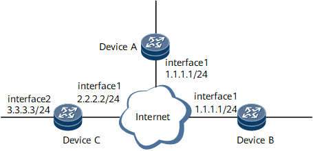
Networking Requirements
As shown in Figure 1, Device A always receives excessive packets and thus the volume of the traffic sent to Device A must be restricted.

Configuration Notes
These functions, however, are assumed to be disabled in this configuration example.
Configuration Roadmap
The configuration roadmap is as follows:
On Device A, define a blacklist and limit the rate of sending packets to the CPU by setting the CAR.
On Device B, configure TCP/IP attack defense, application layer association, and attack source tracing.
On Device C, configure management plane protection.
Recommended Configuration
- Collect and classify protocols on the device. The system matches traffic to be sent to the CPU in sequence and checks the TCP/IP attack packets first. If the packets match the blacklist, the system discards the packets.
- Add valid protocol packets and the service packet that needs protection to the whitelist or user-define flow.
- Add the attack, invalid or unknown packets to the blacklist. Minimize the bandwidth for them or directly drop them.
Data Preparation
To complete the configuration, you need the following data:
Number of the attack defense policy
Index of the packet to be sent to the CPU, number of the user-defined flow
CIR and CBS values of the packet to be sent
Sampling rate and file name for saving information about attack source tracing
Slot number of the interface board where board-level management plane protection is to be applied
Type and number of the interface where interface-level management plane protection is to be applied
Number of the interface board to which the attack defense policy is to be applied
Procedure
- Configure an IP address for each interface. The configuration details are not mentioned here.
- Configure the sending rule for the blacklist on Device A.
<DeviceA> system-view
[~DeviceA] acl 2001
[*DeviceA-acl4-basic-2001] rule deny fragment-type fragment
[*DeviceA-acl4-basic-2001] commit
[~DeviceA-acl4-basic-2001] quit
[~DeviceA] cpu-defend policy 4
[*DeviceA-cpu-defend-policy-4] blacklist acl 2001
[*DeviceA-cpu-defend-policy-4] car blacklist cir 1000
[*DeviceA-cpu-defend-policy-4] priority blacklist low
[*DeviceA-cpu-defend-policy-4] car total-packet 5000
[*DeviceA-cpu-defend-policy-4] alarm drop-rate blacklist enable
[*DeviceA-cpu-defend-policy-4] alarm drop-rate blacklist interval 60 threshold 1000
[*DeviceA-cpu-defend-policy-4] commit
- On Device B, configure the functions such as TCP/IP attack defense and application layer association to defend against attack packets.
# Configure attack source tracing.
<DeviceB> system-view
[~DeviceB] cpu-defend policy 4
[*DeviceB-cpu-defend-policy-4] attack-source-trace enable
[*DeviceB-cpu-defend-policy-4] attack-source-trace sample-rate 1000
# Configure TCP/IP attack defense.
[*DeviceB-cpu-defend-policy-4] udp-packet-defend enable
[*DeviceB-cpu-defend-policy-4] abnormal-packet-defend enable
# Configure application layer association.
[*DeviceB-cpu-defend-policy-4] application-apperceive default-action min-to-cp
[*DeviceB-cpu-defend-policy-4] commit
- On Device C, configure management plane protection.
# Configure global management plane protection.
<DeviceC> system-view
[~DeviceC] ma-defend global-policy
[*DeviceC-app-sec-global] protocol bgp permit
[*DeviceC-app-sec-global] enable
[~DeviceC-app-sec-global] quit
# Configure board-level management plane protection.
[~DeviceC] ma-defend slot-policy 4
[*DeviceC-app-sec-slot-4] protocol ftp permit
[~DeviceC-app-sec-slot-4] quit
[~DeviceC] slot 1
[~DeviceC-slot-1] ma-defend-slot 4
[*DeviceC-slot-1] commit
[~DeviceC-slot-1] quit
# Configure interface-level management plane protection.
[~DeviceC] ma-defend interface-policy 4
[*DeviceC-app-sec-interface-4] protocol ospf permit
[*DeviceC-app-sec-interface-4] quit
[~DeviceC] interface gigabitethernet 0/1/8
[~DeviceC-GigabitEthernet0/1/8] ma-defend-interface 4
[*DeviceC-GigabitEthernet0/1/8] commit
[~DeviceC-GigabitEthernet0/1/8] quit
- Apply the attack defense policy.
Apply attack defense policy 4 on interface board 1 of Device A.
<DeviceA> system-view
[~DeviceA] slot 1
[*DeviceA-slot-1] cpu-defend-policy 4
[*DeviceA-slot-1] commit
Apply attack defense policy 4 on interface board 1 of Device B.
<DeviceB> system-view
[~DeviceB] slot 1
[~DeviceB-slot-1] cpu-defend-policy 4
[*DeviceB-slot-1] commit
- Verify the configuration.
# Run the display cpu-defend policy 4 command to check the rules configured in attack defense policy 4.
Configuration example of User Defined Flow
The following table lists a configuration planning for user defined flow. You can modify the list or add more items based on the actual network conditions.
Class |
Matched Content |
Priority |
Protection Action |
Remarks |
|---|---|---|---|---|
Trusted network segment |
Source IP address |
High |
Add source IP addresses on the trusted network segment to user-defined list 1. |
Use ACL 3330 to filter packets containing source IP addresses on the trusted network segment. |
Set the rate limit for user-defined list 1 to 1 Mbit/s. |
||||
Routing protocol |
BGP |
High |
Add BGP packets to user-defined list 2. |
Use ACL 3331 to filter packets containing the IP address of the BGP peer. |
Set the rate limit for user-defined list 2 to 1 Mbit/s. |
||||
LDP |
High |
Add LDP packets to user-defined list 3. |
Use ACL 3332 to filter packets containing the source IP addresses of the LDP peer and directly connected interface. |
|
Set the rate limit for user-defined list 3 to 1 Mbit/s. |
||||
OSPF |
High |
Add OSPF and RIP packets to user-defined list 4. |
Use ACL 3333 to filter packets containing the source IP address of the OSPF neighbor. |
|
RIP |
Set the rate limit for user-defined list 4 to 1 Mbit/s. |
|||
ISIS |
NA |
NA |
No ACL is involved because IS-IS is a Layer 2 protocol. CPU defend policy supports basic ACL and advanced ACL, that is, only supports to filter L3 and L4 protocol. |
|
Protocol ensuring reliability |
VRRP |
Medium |
Add VRRP packets to user-defined list 5. |
Use ACL 3334 to filter VRRP packets. |
Set the rate limit for user-defined list 5 to 1 Mbit/s. |
||||
Multicast protocol |
PIM |
Medium |
Add PIM, IGMP, and MSDP packets to user-defined list 6. Set the rate limit for user-defined list 6 to 1 Mbit/s. |
Use ACL 3335 to filter PIM, IGMP, and MSDP packets. |
IGMP |
||||
MSDP |
||||
Reserved multicast addresses |
Medium |
Add reserved multicast addresses to user-defined list 7. Set the rate limit for user-defined list 7 to 1 Mbit/s. |
Use ACL 3336 to filter packets containing the following reserved multicast addresses:
|
|
Access protocol |
SSH |
Medium |
Add Telnet packets to user-defined list 8. |
Use ACL 3337 to filter Telnet packets. |
TELNET |
Set the rate limit for user-defined 8 to 512 kbit/s. |
|||
FTP |
Low |
Add FTP and TFTP packets to user-defined list 9. |
Use ACL 3338 to filter FTP and TFTP packets. |
|
TFTP |
Set the rate limit for user-defined 9 to 512 kbit/s. |
|||
FTP-DATA |
Low |
Add FTP-DATA to user-defined list 10. |
Use ACL 3339 to filter FTP-DATA. |
|
Do not set the rate limit for user-defined list 10. |
||||
Network management protocols |
SNMP |
Low |
Add SNMP packets to user-defined list 11. |
Use ACL 3340 to filter SNMP packets. |
Set the rate limit for user-defined list 11 to 1 Mbit/s. |
||||
Service protocol |
TACACS |
Low |
Add TACACS and NTP packets to user-defined list 12. |
Use ACL 3341 to filter TACACS (including standard TACACS and Huawei TACACS) and NTP packets. |
NTP |
Set the rate limit for user-defined 12 to 512 kbit/s. |
|||
Tool protocol |
ICMP |
Low |
Add ICMP packets to user-defined list 13. |
Use ACL 3342 to filter ICMP TTL Exceeded packets, ICMP Port-unreachable packets, ICMP Echo packets, and ICMP Echo Reply packets. |
Set the rate limit for user-defined list 13 to 1 Mbit/s. |
||||
Other |
Unknown or attack packets |
Low |
Reserve 256 KB best-effort bandwidth in the blacklist. |
Use ACL 3360 to filter unknown and attack packets. |

This document just introduces a configuration example. The solution and data of your actual network conditions, such as the running protocols, the IP addresses of the protocols, may be different from this example. Please check and keep them consistent with your network.
If your network needs more configurations, such as more BGP peer, OSPF peer, modify or add the rules in the relative ACL.
1. Add the source IP addresses on the trusted network segment to ACL 3330. |
Source IP addresses on the trusted network segment indicate the IP addresses allowed to access the device Example: acl number 3330 rule permit ip source 10.1.1.0 0.0.0.255 rule permit ip source 10.1.2.0 0.0.0.255 ... If there are new trusted network segments, add them to ACL 3330. For example, if the network maintenance engineer needs to telnet to the device to troubleshoot, the source IP address needs to be added to this ACL. It is allowed to temporally add rule permit ip instead for an urgency case. Delete the temporal command after the troubleshooting finished. acl number 3330 rule permit ip source 10.1.1.0 0.0.0.255 ... rule permit ip |
2. Add BGP protocol to ACL 3331. |
TCP session in BGP is established based on peer IP addresses. Therefore, add the peer IP address to the ACL. The peer IP address can be obtained from the following commands: <HUAWEI> display bgp peer
BGP local router ID : 1.1.1.33
Local AS number : 100
Total number of peers : 1 Peers in established state : 1
Peer V AS MsgRcvd MsgSent OutQ Up/Down State PrefRcv
10.1.1.31 4 100 3 3 0 00:01:16 Established 0
10.1.1.32 4 100 3 3 0 00:05:20 Established 0
In the preceding information, the device has two BGP peers and the IP addresses of the BGP peers are 10.1.1.31 and 10.1.1.32. So the ACL rule is configured as follows. Precise configuration based on source IP address and port number: acl number 3331 rule permit tcp source 10.1.1.31 0 destination-port eq bgp rule permit tcp source 10.1.1.31 0 source-port eq bgp rule permit tcp source 10.1.1.32 0 destination-port eq bgp rule permit tcp source 10.1.1.32 0 source-port eq bgp Simplified configuration based only on port-number: acl number 3331 rule permit tcp destination-port eq bgp rule permit tcp source-port eq bgp NOTE:
If there are more BGP peers, add a rule for each peer for precise configuration. Simplified configuration has less security. |
3. Add LDP protocol to ACL 3332. |
LDP protocol uses TCP to set up session and UDP to discover peers and maintain peer relationships. This process involves not only the peer IP address, but also the IP address of the directly connected interface. These IP addresses need to be added to ACL.
Configuration summary:
NOTE:
|
4. Add OSPF or RIP protocol to ACL 3333. |
OSPF sets up neighbor based on interface IP address, so the interface IP address needs to be added to ACL.
NOTE:
|
5. Add VRRP protocol to ACL 3334. |
VRRP is based on IP and its protocol ID is 112. VRRP peer sends packets with the peer virtual IP address. So, add the peer virtual IP address and the protocol ID to ACL.
NOTE:
|
6. Add multicast protocol to ACL 3335. |
Multicast protocols include PIM (protocol number 103), IGMP (protocol number 2), and MSDP (protocol number 639). acl number 3335 rule permit 103 rule permit igmp rule permit udp destination-port eq 639 rule permit udp source-port eq 639 rule permit tcp destination-port eq 639 rule permit tcp source-port eq 639 |
7. Add reserved multicast addresses to ACL 3336. |
The reserved multicast addresses are 224.0.0.0/24 and 255.255.255.255/0. acl number 3336 rule permit ip destination 224.0.0.0 0.0.0.255 rule permit ip destination 255.255.255.255 0 |
8. Add Telnet and SSH protocols to ACL 3337. |
Telnet and SSH are TCP-based protocols used for normal login or console login. The two protocols are very important and are therefore added to an independent ACL for protection. Both source port and destination port need to be specified. The port number of SSH is 22. Precise configuration based on source IP address and port number: acl number 3337 rule permit tcp source 10.97.3.0 0.0.0.255 source-port eq telnet rule permit tcp source 10.97.3.0 0.0.0.255 destination-port eq telnet rule permit tcp source 10.97.3.0 0.0.0.255 source-port eq 22 rule permit tcp source 10.97.3.0 0.0.0.255 destination-port eq 22 Simplified configuration based only on port number: acl number 3337 rule permit tcp source-port eq telnet rule permit tcp destination-port eq telnet rule permit tcp source-port eq 22 rule permit tcp destination-port eq 22 NOTE:
|
9. Add FTP and TFTP protocols to ACL 3338. |
FTP is TCP-based protocol, and TFTP is UDP-based protocol. Each source IP address of the FTP/TFTP user needs three rules, as shown in the following commands. Precise configuration based on source IP address and port number: acl number 3338 rule permit udp source 10.97.3.0 0.0.0.255 destination-port eq tftp rule permit tcp source 10.97.3.0 0.0.0.255 source-port eq ftp rule permit tcp source 10.97.3.0 0.0.0.255 destination-port eq ftp Simplified configuration based only on port number: acl number 3338 rule permit udp destination-port eq tftp rule permit tcp source-port eq ftp rule permit tcp destination-port eq ftp NOTE:
Inaccurate configuration has less security. |
10. Add FTP-DATA protocol to ACL 3339. |
FTP-DATA is used to transmit data. When the device gets files from remote endpoint, the data is sent to CPU. The transmission rate must be ensured, that is, the bandwidth for the FTP-DATA cannot be limit. Therefore, add FTP-DATA to an independent ACL for protection. Precise configuration based on source IP address and port number: acl number 3339 rule permit tcp source 10.97.3.0 0.0.0.255 source-port eq ftp-data rule permit tcp source 10.97.3.0 0.0.0.255 destination-port eq ftp-data Simplified configuration based only on port number: acl number 3339 rule permit tcp source-port eq ftp rule permit tcp destination-port eq ftp NOTE:
Simplified configuration has less security. |
11. Add SNMP protocol to ACL 3340. |
An NMS is deployed on most live networks. An NMS server sends a large number of UDP request packets to devices, and devices send UDP reply packets through SNMP ports. As a large number of packets need to be exchanged, these devices need to be added to an independent ACL for protection. Configuration example: Precise configuration based on source IP address and port number: acl number 3340 rule permit udp source 10.43.48.0 0.0.0.255 destination-port eq snmp rule permit udp source 10.97.3.0 0.0.0.255 destination-port eq snmp Simplified configuration based only on port number: acl number 3340 rule permit udp destination-port eq snmp NOTE:
|
12. Add TACACS and NTP protocol to ACL 3341. |
TACACS and NTP are service-oriented protocols. The NTP port number is 123. TACACS have two types: Huawei-specific TCP-based TACACS and UDP-based standard TACACS. It is recommended that you add both types to the ACL. Configuration example: Precise configuration based on source IP address and port number: acl number 3341 rule permit udp source 10.43.0.0 0.0.255.255 source-port eq 123 rule permit udp source 10.43.0.0 0.0.255.255 destination-port eq 123 rule permit tcp source 10.43.53.20 0 source-port eq tacacs rule permit tcp source 10.43.49.20 0 destination-port eq tacacs rule permit udp source 10.43.53.20 0 source-port eq tacacs-ds rule permit udp source 10.43.49.20 0 destination-port eq tacacs-ds Simplified configuration based only on port number: acl number 3341 rule permit udp source- port eq 123 rule permit udp destination- port eq 123 rule permit tcp source-port eq tacacs rule permit tcp destination-port eq tacacs rule permit udp source-port eq tacacs-ds rule permit udp destination-port eq tacacs-ds NOTE:
Simplified configuration has less security. |
13. Add ICMP Ping-LSP and Tracert to ACL 3342. |
acl number 3342 rule permit icmp icmp-type echo rule permit icmp icmp-type echo-reply rule permit icmp icmp-type ttl-exceeded rule permit icmp icmp-type port-unreachable rule permit icmp icmp-type Fragmentneed-DFset rule permit icmp rule permit udp destination-port range 33434 33678 ///ping-lsp rule permit udp destination-port eq 3503 ///tracert |
14. Add BFD protocol to ACL 3343. |
BFD is UDP-based protocol and its port number is 3784. Precise configuration based on source IP address and port number: acl number 3343 rule permit udp source 10.43.0.0 0.0.255.255 destination -port eq 3784 rule permit udp source 10.43.0.0 0.0.255.255 source -port eq 3784 Simplified configuration based only on port number: acl number 3343 rule permit udp destination-port eq 3784 rule permit udp source-port eq 3784 NOTE:
Simplified configuration has less security. |
Example for configuring the blacklist rule
Add invalid or unknown protocols to ACL 3360. |
ACL 3330 to ACL 3343 are used to filter normal protocol packets and packets on the trusted network segment. Other packets are considered invalid or unknown. Use ACL 3360 to filter invalid or unknown packets. The configuration is as follows: acl number 3360 rule permit ip rule permit igmp rule permit 103 ///PIM protocol rule permit ospf Result:
|
The packets to be sent to the CPU comply with the following match sequence by default: TCPSYN packets, packet fragments, dynamic link protection, management protocol ACL, whitelist, blacklist, and user-defined flow. In the preceding example, packets need to match against the user-defined flow before the blacklist. Therefore, run the command to adjust the match sequence as required. # cpu-defend policy 10 process-sequence tcpsyn-flood fragment-flood dynamic-link-protection management-acl whitelist user-defined-flow blacklist # |