Example for Configuring Traffic Suppression over a VSI PW
This section provides an example for configuring traffic suppression over a VSI PW, including the networking requirements, configuration roadmap, configuration procedure, and configuration files.
Networking Requirements
On the Ethernet, on the one hand, you need to manage user traffic and properly allocate bandwidths to users; on the other hand, for the sake of security, you need to suppress the unknown unicast traffic, multicast traffic, and broadcast traffic to ensure the normal forwarding of unicast traffic and proper utilization of network bandwidths. If you do not suppress the preceding traffic, the traffic mounts and consumes more network bandwidths, which degrades network performance or even interrupts communications.
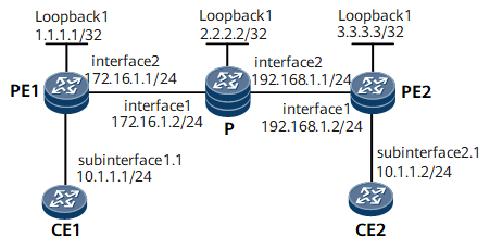
As shown in Figure 1, CE1 and CE2 are in the same virtual private LAN service (VPLS) in Label Distribution Protocol (LDP) mode and can communicate with each other. If you configure traffic suppression on an interface, the broadcast, multicast, and unknown unicast traffic along all the PWs created on the interface is suppressed. To suppress traffic over a specified PW, specify the VSI.

interface1, interface2, subinterface1.1, and subinterface2.1 in this example are GE0/1/0, GE0/1/8, GE0/1/0.1, and 0/1/8.1 respectively.
Device Name |
Interface Name |
Interface IP Address |
Interface MAC Address |
|---|---|---|---|
CE1 |
GE0/1/0.1 |
10.1.1.1/24 |
- |
PE1 |
Loopback1 |
1.1.1.1/32 |
- |
PE1 |
GE0/1/8 |
172.16.1.1/24 |
- |
P |
Loopback1 |
2.2.2.2/32 |
- |
P |
GE0/1/0 |
172.16.1.2/24 |
- |
P |
GE0/1/8 |
192.168.1.1/24 |
- |
PE2 |
Loopback1 |
3.3.3.3/32 |
- |
PE2 |
GE0/1/0 |
192.168.1.2/24 |
- |
CE2 |
GE0/1/8.1 |
10.1.1.2/24 |
- |
Configuration Roadmap
The configuration roadmap is as follows:
Configure the routing protocol on the backbone network.
Set up a remote LDP session between PEs.
Set up a tunnel between PEs to transmit user data.
Enable Multiprotocol Label Switching (MPLS) Layer 2 virtual private network (L2VPN) on the PEs.
Create a VSI on each PE. Specify LDP as the signaling protocol and then bind the VSI to the AC interface.
- Configure traffic suppression over a VSI PW in LDP mode.
Data Preparation
To configure traffic suppression over a VSI PW, you need the following data:
VSI name and VSI ID
IP addresses and a tunnel policy used for setting up a peer relationship
Interfaces bound to the VSI
CIR for broadcast traffic
Procedure
- Configure an Interior Gateway Protocol (IGP).
Open Shortest Path First (OSPF) is used as an example, and detailed configurations are not provided here.
After the configuration is complete, run the display ip routing-table command on PEs and the P. You can view the routes that the devices have learned from each other.
When configuring OSPF, advertise the 32-bit IP addresses of loopback interfaces, which are used as label switching router (LSR) IDs, on PEs and the P.
- Configure basic MPLS functions and LDP.
The configuration details are not provided here. For details, see "MPLS LDP Configuration" in HUAWEI NetEngine 8000 F Series Router Configuration Guide - MPLS.
After the configuration is complete, run the display mpls ldp session command on PEs and the P. The command output shows that Status of the peer relationships between PE1 and the P and between PE2 and the P is Operational, which indicates that the peer relationships have been established. Run the display mpls lsp command to view the label switched path (LSP) status.
- Set up a remote LDP session between PEs.
# Configure PE1.
[~PE1] mpls ldp remote-peer 3.3.3.3
[*PE1-mpls-ldp-remote-3.3.3.3] remote-ip 3.3.3.3
[*PE1-mpls-ldp-remote-3.3.3.3] quit
[*PE1] commit
# Configure PE2.
[~PE2] mpls ldp remote-peer 1.1.1.1
[*PE2-mpls-ldp-remote-1.1.1.1] remote-ip 1.1.1.1
[*PE2-mpls-ldp-remote-1.1.1.1] quit
[*PE2] commit
After the configuration is complete, run the display mpls ldp session command on PEs and the P. The command output shows that Status of the peer relationships between PE1 and the P and between PE2 and the P is Operational, which indicates that the peer relationships have been established.
- Enable MPLS L2VPN on PEs.
# Configure PE1.
[~PE1] mpls l2vpn
[*PE1-l2vpn] quit
[*PE1] commit
# Configure PE2.
[~PE2] mpls l2vpn
[*PE2-l2vpn] quit
[*PE2] commit
- Create a VSI on each PE and configure traffic suppression based on the VSI PW.
# Configure broadcast, multicast, and unknown unicast traffic suppression based on the VSI PW on PE1.
[~PE1] vsi a2 static
[*PE1-vsi-a2] suppression inbound enable
[*PE1-vsi-a2] pwsignal ldp
[*PE1-vsi-a2-ldp] vsi-id 2
[*PE1-vsi-a2-ldp] peer 3.3.3.3
[*PE1-vsi-a2-ldp] peer 3.3.3.3 pw 1
[*PE1-vsi-a2-ldp-pw-1] broadcast-suppression cir 1000
[*PE1-vsi-a2-ldp-pw-1] multicast-suppression cir 1000
[*PE1-vsi-a2-ldp-pw-1] unknown-unicast-suppression cir 1000
[*PE1-vsi-a2-ldp-pw-1] quit
[*PE1-vsi-a2-ldp] quit
[*PE1-vsi-a2] quit
[*PE1] commit
# Configure broadcast, multicast, and unknown unicast traffic suppression based on the VSI PW on PE2.
[~PE2] vsi a2 static
[*PE2-vsi-a2] suppression inbound enable
[*PE2-vsi-a2] pwsignal ldp
[*PE2-vsi-a2-ldp] vsi-id 2
[*PE2-vsi-a2-ldp] peer 1.1.1.1
[*PE2-vsi-a2-ldp] peer 1.1.1.1 pw 1
[*PE2-vsi-a2-ldp-pw-1] broadcast-suppression cir 1000
[*PE2-vsi-a2-ldp-pw-1] multicast-suppression cir 1000
[*PE2-vsi-a2-ldp-pw-1] unknown-unicast-suppression cir 1000
[*PE2-vsi-a2-ldp-pw-1] quit
[*PE2-vsi-a2-ldp] quit
[*PE2-vsi-a2] quit
[*PE2] commit
- Bind the VSI to the AC interface on each PE.
# Configure PE1.
[~PE1] interface gigabitethernet0/1/0.1
[*PE1-GigabitEthernet0/1/0.1] shutdown
[*PE1-GigabitEthernet0/1/0.1] vlan-type dot1q 10
[*PE1-GigabitEthernet0/1/0.1] l2 binding vsi a2
[*PE1-GigabitEthernet0/1/0.1] undo shutdown
[*PE1-GigabitEthernet0/1/0.1] quit
[*PE1] commit
# Configure PE2.
[~PE2] interface gigabitethernet0/1/8.1
[*PE2-GigabitEthernet0/1/8.1] shutdown
[*PE2-GigabitEthernet0/1/8.1] vlan-type dot1q 10
[*PE2-GigabitEthernet0/1/8.1] l2 binding vsi a2
[*PE2-GigabitEthernet0/1/8.1] undo shutdown
[*PE2-GigabitEthernet0/1/8.1] quit
[*PE2] commit
- Configure the CEs.
# Configure CE1.
<HUAWEI> sysname CE1
<HUAWEI> commit
[~CE1] interface gigabitethernet0/1/0.1
[*CE1-GigabitEthernet0/1/0.1] shutdown
[*CE1-GigabitEthernet0/1/0.1] vlan-type dot1q 10
[*CE1-GigabitEthernet0/1/0.1] ip address 10.1.1.1 255.255.255.0
[*CE1-GigabitEthernet0/1/0.1] undo shutdown
[*CE1-GigabitEthernet0/1/0.1] quit
[*CE1] commit
# Configure CE2.
<HUAWEI> sysname CE2
<HUAWEI> commit
[~CE2] interface gigabitethernet0/1/0.1
[*CE2-GigabitEthernet0/1/0.1] shutdown
[*CE2-GigabitEthernet0/1/0.1] vlan-type dot1q 10
[*CE2-GigabitEthernet0/1/0.1] ip address 10.1.1.2 255.255.255.0
[*CE2-GigabitEthernet0/1/0.1] undo shutdown
[*CE2-GigabitEthernet0/1/0.1] quit
[*CE1] commit
- Verify the configuration.
After the configuration is complete, run the display vsi name a2 verbose command on PE1. The command output shows that VSI named a2 establishes a PW to PE2 and the VSI is Up.
[PE1] display vsi name a2 verbose
 ***VSI Name               : a2
    Administrator VSI      : no
    Isolate Spoken         : disable
    VSI Index              : 0
    PW Signaling           : ldp
    Member Discovery Style : static
    PW MAC Learn Style     : unqualify
    Encapsulation Type     : vlan
    MTU                    : 1500
    Diffserv Mode          : uniform
    Service Class          : --
    Color                  : --
    DomainId               : 255
    Domain Name            :
    Ignore AcState         : disable
    Multicast Fast Swicth  : disable
    Create Time            : 0 days, 3 hours, 30 minutes, 31 seconds
    VSI State              : up
    VSI ID                 : 2
   *Peer Router ID         : 3.3.3.3
    primary or secondary   : primary
    ignore-standby-state   : no
    VC Label               : 18
    Peer Type              : dynamic
    Session                : up
    Tunnel ID              : 0x0000000001004c4b82
    Broadcast Tunnel ID    : --
    Broad BackupTunnel ID  : --
    CKey                   : 6
    NKey                   : 5
    StpEnable              : 0
    PwIndex                : 0
    Interface Name         : GigabitEthernet0/1/0.1
    State                  : up
    Last Up Time           : 2012/10/10 10:14:46
    Total Up Time          : 0 days, 0 hours, 1 minutes, 2 seconds
   **PW Information:
   *Peer Ip Address        : 3.3.3.3
    PW State               : up
    Local VC Label         : 18
    Remote VC Label        : 18
    PW Type                : label
    Tunnel ID              : 0x0000000001004c4b82
    Broadcast Tunnel ID    : --
    Broad BackupTunnel ID  : --
    Ckey                   : 1
    Nkey                   : 1610612838
    Main PW Token          : 0x0
    Slave PW Token         : 0x0
    Tnl Type               : LdP
    OutInterface           : LDP LSP
    Backup OutInterface    :
    Stp Enable             : 0
    PW Last Up Time        : 2012-10-10 10:15:59
    PW Total Up Time       : 0 days, 0 hours, 1 minutes, 3 seconds
Ping CE2 (10.1.1.2) from CE1 (10.1.1.1). The ping operation succeeds.
[CE1] ping 10.1.1.2
  PING 10.1.1.2: 56  data bytes, press CTRL_C to break
    Reply from 10.1.1.2: bytes=56 Sequence=1 ttl=255 time=90 ms
    Reply from 10.1.1.2: bytes=56 Sequence=2 ttl=255 time=77 ms
    Reply from 10.1.1.2: bytes=56 Sequence=3 ttl=255 time=34 ms
    Reply from 10.1.1.2: bytes=56 Sequence=4 ttl=255 time=46 ms
    Reply from 10.1.1.2: bytes=56 Sequence=5 ttl=255 time=94 ms
  --- 10.1.1.2 ping statistics ---
    5 packet(s) transmitted
    5 packet(s) received
    0.00% packet loss
    round-trip min/avg/max = 34/68/94 ms
Configuration Files
Configuration file of CE1
#
 sysname CE1
#
interface GigabitEthernet0/1/0
 undo shutdown
#
interface GigabitEthernet0/1/0.1
 undo shutdown
 vlan-type dot1q 10
 ip address 10.1.1.1 255.255.255.0
#
return
Configuration file of CE2
#
 sysname CE2
#
interface GigabitEthernet0/1/0
 undo shutdown
#
interface GigabitEthernet0/1/0.1
 undo shutdown
 vlan-type dot1q 10
 ip address 10.1.1.2 255.255.255.0
#
return
Configuration file of PE1
#
 sysname PE1
#
 mpls lsr-id 1.1.1.1
#
 mpls
#
 mpls l2vpn
#
vsi a2 static
 pwsignal ldp
  vsi-id 2
  peer 3.3.3.3
  peer 3.3.3.3 pw 1
  broadcast-suppression cir 1000
  multicast-suppression cir 1000
  unknown-unicast-suppression cir 1000
 suppression inbound enable
#
mpls ldp
#
 mpls ldp remote-peer 3.3.3.3
 remote-ip 3.3.3.3
#
interface GigabitEthernet0/1/0
 undo shutdown
#
interface GigabitEthernet0/1/0.1
 undo shutdown
 vlan-type dot1q 10
 l2 binding vsi a2
#
interface GigabitEthernet0/1/8
 undo shutdown
 ip address 172.16.1.1 255.255.255.0
 mpls
 mpls ldp
#
interface LoopBack1
 ip address 1.1.1.1 255.255.255.255
#
ospf 1
 area 0.0.0.0
  network 1.1.1.1 0.0.0.0
  network 172.16.1.0 0.0.0.255
#
return
Configuration file of the P
#
 sysname P
#
 mpls lsr-id 2.2.2.2
 mpls
#
mpls ldp
#
interface GigabitEthernet0/1/0
 undo shutdown
 ip address 172.16.1.2 255.255.255.0
 mpls
 mpls ldp
#
interface GigabitEthernet0/1/8
 undo shutdown
 ip address 192.168.1.1 255.255.255.0
 mpls
 mpls ldp
#
interface LoopBack1
 ip address 2.2.2.2 255.255.255.255
#
ospf 1
 area 0.0.0.0
  network 172.16.1.0 0.0.0.255
  network 192.168.1.0 0.0.0.255
  network 2.2.2.2 0.0.0.0
#
return
Configuration file of PE2
#
 sysname PE2
#
 mpls lsr-id 3.3.3.3
 mpls
#
 mpls l2vpn
#
vsi a2 static
 pwsignal ldp
  vsi-id 2
  peer 1.1.1.1
  peer 1.1.1.1 pw 1
  broadcast-suppression cir 1000
  multicast-suppression cir 1000
  unknown-unicast-suppression cir 1000
 suppression inbound enable
#
mpls ldp
#
 mpls ldp remote-peer 1.1.1.1
 remote-ip 1.1.1.1
#
interface GigabitEthernet0/1/0
 undo shutdown
 ip address 192.168.1.2 255.255.255.0
 mpls
 mpls ldp
#
interface GigabitEthernet0/1/8
 undo shutdown
#
interface GigabitEthernet0/1/8.1
 undo shutdown
 vlan-type dot1q 10
 l2 binding vsi a2
#
interface LoopBack1
 ip address 3.3.3.3 255.255.255.255
#
ospf 1
 area 0.0.0.0
  network 3.3.3.3 0.0.0.0
  network 192.168.1.0 0.0.0.255
#
return