Application Scenarios for Defense Against Attacks
Typical Application of Application Layer Association
Flooding of network layer protocol packets is the most common attack on the network. Therefore, application layer association focuses on this type of attack. In the application shown in Figure 1, application layer association defends against flooding attacks on the network layer through association between the protocol enabling status and protocol characteristics and dynamic link protection. This way, application layer association improves the defense capability of the device.
When MAN IP mode is adopted, a host can start a flooding attack on the IP address of the device.
Application of Management and Service Plane Protection
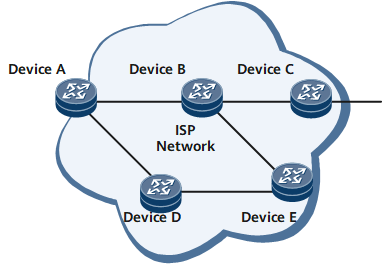
In the application shown in Figure 2, some users attached to the Layer 2 switch may be hackers trying to control the device through Telnet or another management protocol, such as FTP, or trying to attack the device by Telnet flood. In this situation, management and service plane protection is required to discard management packets (including Telnet/FTP/TFTP/SNMP/SSH packets) received from any non-management interfaces. Service packets are treated in a similar manner.
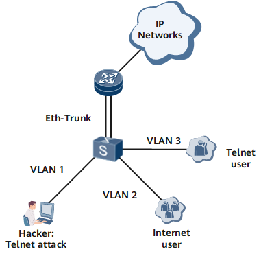
The networking shown in the figure exists on enterprise networks or carriers' networks. A user accesses the Layer 2 switch through an Ethernet interface or dials into the DSLAM through an ADSL and then accesses the Layer 2 switch through the DSLAM. Then, the user accesses the router or Layer 3 switch through a Layer 2 switch and accesses the Internet through the router or switch. An Eth-Trunk is enabled between the router and switch to ensure reliability; the NMS manages the device through the Layer 3 network.
Application of TCP/IP Attack Defense
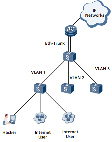
Service routers residing at the network edge are prone to attacks. In the application shown in Figure 3, the NetEngine 8000 F defends itself against attacks by filtering and limiting the rates of malformed packets, fragmented packets, TCP Syn-Flood packets, and UDP-Flood packets.
Application of Local URPF
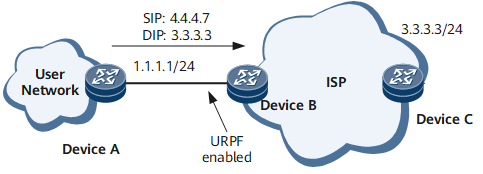
In the application of local URPF shown in Figure 4, customer routers DeviceA and DeviceB are connected.
Packet URPF inspection is enabled onInterface1 of DeviceB to protect the RC against a source address spoofing attack from the customer network. URPF inspection is enabled on Interface1 of DeviceB. A hacker from the client network with the bogus IP address 4.4.4.7 sends a packet to Interface1. The packet with the source address 4.4.4.7 should be received from another interface instead of Interface1. Therefore, the router considers the source address of the packet to be a bogus one and discards the packet.
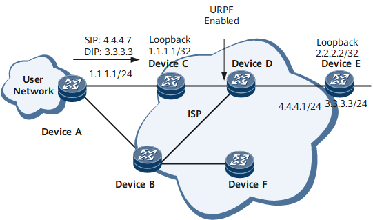
In the application of local URPF shown in Figure 5, to access the Loopback interface whose IP address is 2.2.2.2 on DeviceC from DeviceA, Packets need to pass through DeviceC or DeviceB and DeviceC. That is, to reach the destination IP address 2.2.2.2, a packet can pass through Interface 1 (directly connected to the RC) or Interface 2 (directly connected to the RB).
You can meet this application scenario through local URPF in loose mode. In this mode, DeviceC checks only whether the route of the source address exists and is not concerned with whether the inbound interface matches the outbound interface of the route.
Application of the GTSM
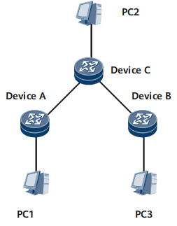
In the application shown in Figure 6, DeviceA and DeviceB are neighboring routers and are directly connected. DeviceA and DeviceC are adjacent routers and are connected through DeviceB. DeviceC is connected to DeviceA via a network, which defines a fixed number of hops (n) from DeviceC to DeviceA.
The TTL field of the packet sent from DeviceB is 255; the TTL field of the packet received by DeviceA is also 255. The TTL field of the packet sent from DeviceC is 255, whereas the TTL field of the packet received by DeviceA from DeviceC is 254. The TTL field of the packet sent from DeviceC is 255, and the TTL field of the packet received by DeviceA from DeviceC is 255-n.
In Figure 6, GTSM is enabled on all the routers.
The valid TTL of the packet received by DeviceA from DeviceB is 255.
The valid TTL of the packet received by DeviceA from DeviceC is 254 or 255.
The valid TTL of the packet received by DeviceA from DeviceC ranges from 255-n to 255.
Packets are sent to the CPU for further processing only if all the preceding conditions are met. Otherwise, the packets are discarded.