Principle of 1588v2 Synchronization
The principles of 1588v2 time synchronization and NTP are the same. The master and slave nodes exchange timing messages, and calculate the message transmission delays in two directions (sending and receiving) according to the receiving and sending timestamps in the exchanged timing messages. If the message transmission delays in two directions are identical, the message transmission delay in one direction (the time offset between the slave and master nodes) equals the delays in two directions divided by 2. Then, the slave node synchronizes with the master node by correcting its local time according to the time offset.
In practice, the delay and jitter on the network need to be taken into account, and the sending and receiving delays are not always identical. Therefore, message-based time synchronization, namely, 1588v2 and NTP, cannot guarantee high synchronization accuracy. For example, NTP can only provide the synchronization accuracy of 10 to 100 ms.
1588v2 and NTP differ in implementation.
NTP runs at the application layer, for example, on the main control board of the NetEngine 8000 F. The delay measured by NTP, in addition to the link delay, includes various internal processing delays, such as the internal congestion queuing, software scheduling, and software processing delays. These make the message transmission delay unstable, causing message transmission delays in two directions to be asymmetric. As a result, the accuracy of NTP-based time synchronization is low.
1588v2 presumes that the link delay is constant or changes so slowly that the change between two synchronization processes can be ignored, and the message transmission delays in two directions on a link are identical. Messages are time-stamped for delay measurement at the physical layer of the interface board. This ensures that time synchronization based on the obtained link delay is extremely accurate.
1588v2 defines two modes for the delay measurement and time synchronization mechanisms, namely, Delay and Peer Delay (PDelay).
Delay Mode
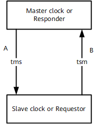
The Delay mode is applied to end-to-end (E2E) delay measurement. Figure 1 shows the delay measurement in Delay mode.
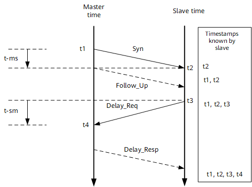

As shown in Figure 1, t-sm and t-ms represent the sending and receiving delays respectively and are presumed to be identical. If they are different, they should be made identical through asymmetric delay correction. For details about asymmetric delay correction, see the following part of this section.
Follow_Up messages are used in two-step mode. Only the one-step mode is described in this part and Follow_UP messages are not mentioned. For details about the two-step mode, see the following part of this section.
A master node periodically sends a Sync message carrying the sending timestamp t1 to the slave node. When the slave node receives the Sync message, it time-stamps t2 to the message.
The slave node periodically sends the Delay_Req message carrying the sending timestamp t3 to the master node. When the master node receives the Delay_Req message, it time-stamps t4 to the message and returns a Delay_Resp message to the slave node.
The slave node receives a set of timestamps, including t1, t2, t3, and t4. Other elements affecting the link delay are ignored.
The message transmission delays of the link between the master and slave nodes in two directions equal (t4 – t1) – (t3 – t2). If the message transmission delays between both nodes are identical, the message transmission delay in one direction is equal to [(t4 – t1) – (t3 – t2)]/2.
If the time offset between the slave clock and the master clock is Offset, then:
t2 - t1 = Delay + Offset
t4 - t3 = Delay - Offset
The offset between the master and slave clocks is [(t2 - t1) - (t4 - t3)]/2.
Based on the time offset, the slave node synchronizes with the master node.
The synchronization is performed repeatedly to ensure that the time on the slave node is the same as that on the master node. Figure 2 shows the networking.
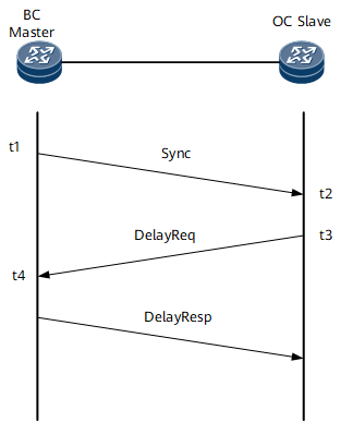
The BC and OC can be directly connected as shown in Figure 2. Alternatively, they can be connected through other TC devices (these devices must be 1588v2 nodes to ensure the accuracy of time synchronization). The TC only transparently transmits 1588v2 messages and corrects the message transmission delay (which requires that the TC identify these 1588v2 messages).
To ensure the high accuracy of 1588v2 time synchronization, it is required that the message transmission delays in two directions between master and slave nodes be stable. Usually, the link delay is stable but the transmission delay on devices is unstable. Therefore, if two nodes performing time synchronization are connected through forwarding devices, the time synchronization accuracy cannot be guaranteed. The solution to the problem is to perform the transmission delay correction on these forwarding devices, which requires that the forwarding devices be TCs.
Figure 3 shows how the transmission delay correction is performed on a TC.
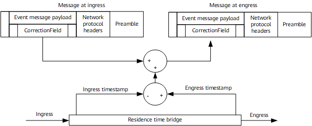
The TC modifies the CorrectionField field of a 1588v2 message on the inbound and outbound interfaces. Specifically, the TC subtracts the timestamp indicating when the 1588v2 message was received on the inbound interface and adds the timestamp indicating when the 1588v2 message was sent from the outbound interface. As such, the forwarding delay of the 1588v2 message on the device is added to the CorrectionField field.
In this manner, the 1588v2 message exchanged between the master and slave nodes, when passing through multiple TCs, carry message transmission delays of all TCs in the CorrectionField field. When the value of the CorrectionField field is deducted, the value obtained is the link delay, ensuring high accuracy time synchronization.
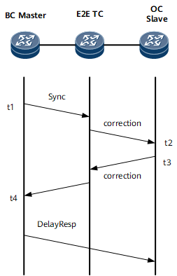
A TC that records the transmission delay from end to end as described above is the E2E TC. Time synchronization in Delay mode can be applied only to E2E TCs. Figure 4 shows how the BC/OC and E2ETC are connected and how 1588v2 operates.
PDelay Mode
When performing time synchronization in PDelay mode, the slave node deducts both the message transmission delay and upstream link delay. This requires that adjacent devices perform the delay measurement in PDelay mode to enable each device on the link to know its upstream link delay. This can be achieved by running the peer delay protocol between adjacent devices. Figure 5 shows the delay measurement in PDelay mode.
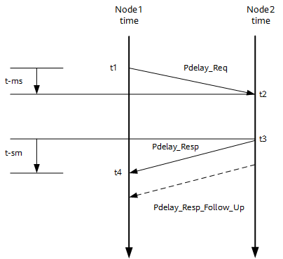
As shown in Figure 1, t-sm and t-ms represent the sending and receiving delays respectively and are presumed to be identical. If they are different, they should be made identical through asymmetric delay correction. For details of asymmetric delay correction, see the following part of this section.
Follow_Up messages are used in two-step mode. In this part, the one-step mode is described and Follow_UP messages are not mentioned. For details of the two-step mode, see the following part of this section.
Node 1 periodically sends a PDelay_Req message carrying the sending timestamp t1 to node 2. When the PDelay_Req message is received, node 2 time-stamps t2 to the PDelay_Req message. Then, node 2 sends a PDelay_Resp message carrying the sending timestamp t3 to node 1. When the PDelay_Resp message is received, node 1 time-stamps t4 to the PDelay_Resp message.
Node 1 obtains a set of timestamps, including t1, t2, t3, and t4. Other elements affecting the link delay are ignored.
The message transmission delays in two directions on the link between node 1 and node 2 equal (t4 – t1) – (t3 – t2).
If the message transmission delays in two directions on the link between node 1 to node 2 are identical, the message transmission delay in one direction equals [(t4 – t1) – (t3 – t2)]/2.
The delay measurement in PDelay mode does not differentiate between the master and slave nodes. All nodes send PDelay messages to their adjacent nodes to calculate adjacent link delay. This calculation process repeats and the message transmission delay in one direction is updated accordingly.
The delay measurement in PDelay mode does not trigger time synchronization. To implement time synchronization, the master node needs to periodically send Sync messages to the slave node and the slave node receives the t1 and t2 timestamps. The slave node then deducts the message transmission delay on the link from the master node to the slave node. The obtained t2-t1-CorrectionField is the time offset between the slave and master nodes. The slave node uses the time offset to synchronize with the master node. Figure 6 shows how time synchronization is implemented in PDelay mode in the scenario where the BC and OC are directly connected.
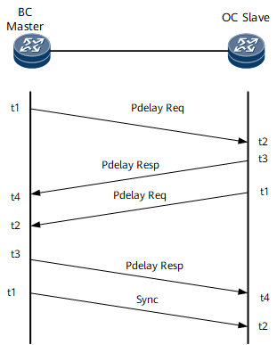
The BC and OC can be directly connected as shown in Figure 6.
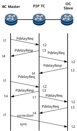
Alternatively, the BC and OC can be connected through other device functioning as TCs to ensure the accuracy of time synchronization. The TC only transparently transmits 1588v2 messages and corrects the message transmission delay (which requires that the TC identify these 1588v2 messages). Unlike delay correction on the E2ETC, delay correction on the P2PTC involves the correction of both transmission delay and upstream link delay. Figure 7 shows how transmission delay correction is performed on a P2PTC.
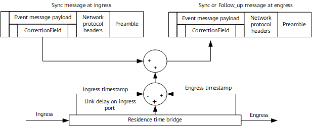
Figure 8 shows how the BC/OC and P2PTC are connected and how 1588v2 operates.
one-step/two-step
In one-step mode, both the Sync messages for time synchronization in Delay mode and PDelay_Resp messages for time synchronization in PDelay mode are stamped with a sending time.
In two-step mode, Sync messages for time synchronization in Delay mode and PDelay_Resp messages for time synchronization in PDelay mode are not stamped with a sending time. The sending time is carried in Follow_Up and PDelay_Resp_Follow_Up messages.
Asymmetric Correction
Theoretically, 1588v2 requires the message transmission delays in two directions on a link to be symmetrical. Otherwise, the algorithms of 1588v2 time synchronization cannot be implemented. In actual implementation, however, the bidirectional delays of a link may be asymmetric due to link or device attributes. For example, the transmit and receive delays are inconsistent between a link and the location where a timestamp is added. To solve the problem, 1588v2 provides an asymmetric delay correction mechanism. Figure 9 shows the asymmetric delay correction mechanism.
Usually, t-ms is identical with t-sm. If they are different, the user can set a delay offset between them if the delay offset is constant and obtainable by measurement device. 1588v2 performs the time synchronization calculation according to the asymmetric correction value. In this manner, a high level of time synchronization accuracy can be achieved on an asymmetric-delay link.
Packet Encapsulation
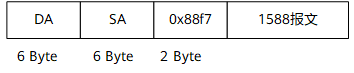
Layer 2 multicast encapsulation through a multicast MAC address
The EtherType field is 0x88F7, and the multicast MAC address is 01-80-C2-00-00-0E (in PDelay messages) or 01-1B-19-00-00-00 (in non-PDelay messages).
1588v2 recommends that the Layer 2 multicast encapsulation mode be used. The NetEngine 8000 F supports Layer 2 multicast encapsulation with tags. Figure 10 shows the Layer 2 multicast encapsulation without tags.
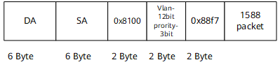
Figure 11 shows Layer 2 multicast encapsulation with tags.
Layer 3 unicast encapsulation through unicast UDP
The destination UDP port number is 319 or 320, depending on the types of 1588v2 messages.
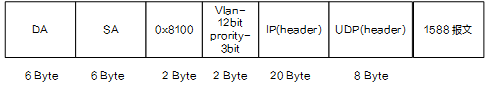
Currently, it is recommended that Huawei base stations adopt Layer 3 unicast encapsulation. The IP clock server consists of multiple BTSs and uses unicast UDP packets to exchange 1588v2 protocol packets. Figure 12 shows Layer 3 unicast encapsulation without tags.
Figure 13 shows Layer 3 unicast encapsulation with tags.
Layer 3 multicast encapsulation through multicast UDP
Layer 2 unicast encapsulation through a unicast MAC address

The NetEngine 8000 F supports Layer 2 multicast encapsulation, Layer 3 unicast encapsulation, Layer 3 multicast encapsulation, and Layer 2 unicast encapsulation.
BITS Interface
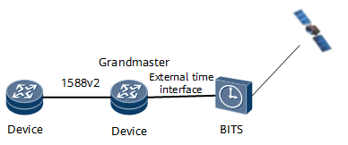
1588v2 enables clock nodes to synchronize with each other, but cannot enable them to synchronize with Greenwich Mean Time (GMT). If the clock nodes need to synchronize with GMT, an external time source is required. That is, the GM needs to be connected to an external time source to obtain the reference time in non-1588v2 mode.
Currently, the external time sources are from satellites, such as the GPS from the U.S.A, Galileo from Europe, GLONASS from Russia, and Beidou from China. Figure 14 shows how the GM and an external time source are connected.
The NetEngine 8000 F provides one type of external clock or time interfaces:
RJ45 port (using a 120 Ohm shielded cable)
The two RJ45 ports function as an external clock port and an external time port respectively, providing the following clock or time signals:
- 2 MHz clock signal (Differential level with one line clock input and one line clock output)
- 2 Mbit/s clock signal (Differential level with one line clock input and one line clock output)
- DC level shifter (DCLS) time signal (RS422 differential level with one line clock input + one line clock output)
- 1 pps + TOD time signal (RS422 differential level with one line time input)
- 1 pps + TOD time signal (RS422 differential level with one line time output)
Clock Synchronization
In addition to time synchronization, 1588v2 can be used for clock synchronization, that is, frequency recovery can be achieved through 1588v2 messages.
1588v2 time synchronization in Delay or PDelay mode requires the device to periodically send Sync messages to its peer.
The sent Sync message carries a sending timestamp. After receiving the Sync message, the peer adds a receiving timestamp to it. When the link delay is stable, the two timestamps change at the same pace. If the receiving timestamp changes are faster or slower, it indicates that the clock of the receiving device runs faster or slower than the clock of the sending device. In this case, the clock of the receiving device needs to be adjusted. When this occurs, the frequencies of the two devices are synchronized.
The frequency restored through 1588v2 messages has a lower accuracy than the frequency restored through synchronous Ethernet. Therefore, it is recommended that you perform frequency synchronization through synchronous Ethernet and time synchronization through 1588v2.
1588v2 restores the frequency in the following modes:
Hop-by-hop
In hop-by-hop mode, all devices on a link are required to support 1588v2. The frequency recovery in this mode is highly accurate. In the case of a small number of hops, the frequency recovery accuracy can meet the requirement of ITU-T G.813 (stratum 3 standard).
End-to-end (Delay and jitter may occur on the transit network.)
In end-to-end mode, the forwarding devices do not need to support 1588v2, and the delay of the forwarding path is only required to meet a specified level, for example, less than 20 ms. The frequency recovery accuracy in this mode is low, and can meet only the requirements of the G.8261 and base stations (50 ppb) rather than that of the stratum 3 clock standard.
To achieve high frequency recovery accuracy, 1588v2 requires Sync messages to be sent at a high rate of at least 100 packets/s.
The NetEngine 8000 F meets the following clock standards:
G.813 and G.823 for external clock synchronization
G.813 for SDH clock (including c-STM-1).
G.8261 and G.8262 for synchronous Ethernet clocks
G.8261 and G.823/G.824 for frequency recovery through 1588v2 messages
At present, the NetEngine 8000 F supports frequency recovery through 1588v2 messages in hop-by-hop mode, rather than in end-to-end or inter-packet delay variation (PDV) network mode. It is compliant with G.8261 and G.823/G.824, but is not committed to be compliant with G.813 and G.8262.