PPPoE Application
PPPoE Access for IPv4 Users
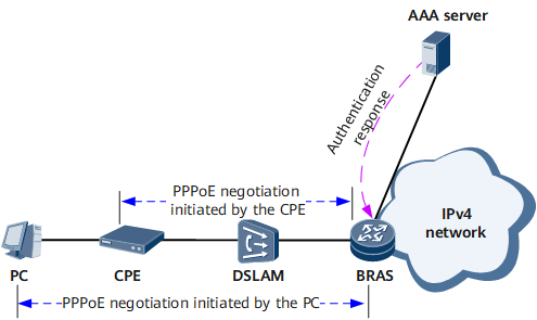
After a user dials up to a BRAS using PPPoE, the BRAS assigns an IPv4 address to the user. Then the user can use the assigned IPv4 address to access IPv4 networks. The PPPoE access process shown on the network in Figure 1 is as follows:
An IPv4 user terminal (PC) initiates PPPoE negotiation with the BRAS through the CPE for a session ID.
The BRAS generates a unique session ID and sends it to the PC to complete PPPoE negotiation. Then PPP negotiation starts with LCP negotiation.
After LCP negotiation is completed, the PPP authentication stage starts. The BRAS initiates an authentication request to the authentication server (AAA server).
After the authentication succeeds, IPCP negotiation starts. The CPE obtains a public IPv4 address from the BRAS.
The PC obtains an internal address from the CPE and uses the internal address to access the CPE. The CPE then uses NAT to convert the internal address to the public IPv4 address assigned by the BRAS, allowing the PC to access the external IPv4 network.
PPPoE negotiation can also be initiated from a PC directly to a BRAS without the participation of a CPE. In this scenario, the PC obtains a public IPv4 address directly from the BRAS to access external networks.
PPPoE Access for IPv6 Users
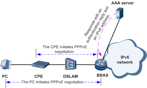
After a user dials up to a BRAS using PPPoE, the BRAS assigns an IPv6 address to the user. Then the user can use the assigned IPv6 address to access IPv6 networks.
As shown in Figure 2, an IPv6 user terminal (PC) initiates PPPoE negotiation with the BRAS directly or through the CPE. The PC uses IPv6CP to apply for an interface ID. Then the PC or CPE generates an LLA based on the interface ID assigned by the BRAS. The PC also uses ND or DHCPv6 to obtain an IPv6 prefix and generates an IPv6 address based on the obtain IPv6 prefix and the interface ID.
Point-to-Point Protocol over Ethernet over VLAN (PPPoEoV)
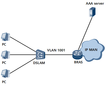
In PPPoEoV services, the Ethernet interface card of a PC encapsulates PPP packets into PPPoE packets, and then sends them to a LAN switch. The LAN switch adds a VLAN tag to each of the PPPoE packets, which are then called PPPoEoV packets, and sends the PPPoEoV packets to the device.
Figure 3 shows the typical networking model of PPPoEoV services. In this model, a PC accesses the Ethernet interface on the device through a switch.
BRAS Access Through L2VPN Termination
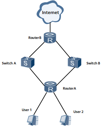
Router B uses OSPF to exchange traffic with Router A through interfaces on multiple boards in load-balancing mode. Traffic from the same user may be sent from different boards. Router B uses PBR to send traffic from the same user but different boards through the backplane to the same authentication board. In the preceding process, VE interfaces' internal loopback is required to support BRAS access through L2VPN termination, so that user authentication is complete after service traffic enters boards again.