Application Scenarios for L2TP Access
Two Typical L2TP Tunnel Modes
Figure 1 shows the mode of the tunnel between the remote system or the LAC client (the host running L2TP) and the LNS.
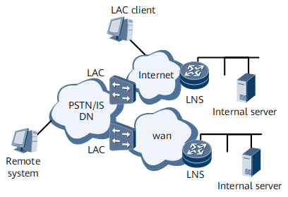
Connections can be set up in either of the following modes:
NAS-initialized mode
A remote user initiates a connection, and the remote system dials in to the LAC over the PSTN/ISDN. Then, the LAC sends a request over the Internet to the LNS for setting up a tunnel. The LNS is responsible for assigning an address to the dial-in user. Either the LNS or the agent at the LAC side can authenticate the remote dial-in user and account the services of the user.
The NAS-initialized mode features the following:Users must access the Internet in PPP mode (for example, through PPPoE).
The carrier's access device (mainly referring to the BAS) needs to be configured with the VPN service. Users need to apply to the carrier for the VPN service.
An L2TP tunnel is set up between the LAC and the LNS, and an L2TP tunnel can bear multiple sessions.
In NAS-initialized mode, as shown in Figure 2, LAN users are connected to a switch; the switch is connected to a NetEngine 8000 F (or multiple users are directly connected to a NetEngine 8000 F); the NetEngine 8000 F is connected to the LAC through PPP or PPPoE.
Client-initialized mode
An LAC client that supports L2TP directly initiates a connection. The client needs to know the IP address of the LNS. The LAC client can directly send a request to the LNS for setting up a tunnel without the LAC. After receiving the request, the LNS authenticates the LAC client according to the user name and password. If the LAC client passes the authentication, the LNS assigns a private IP address to the LAC client.
The client-initialized mode features the following:Users need to install the L2TP dial-in software. Users can also dial in through the VPN dial-in software of the Windows operating system.
There are no limitations of how and where users access the network, and no ISP is required.
An L2TP tunnel is set up between the client and the LNS, and an L2TP tunnel can bear only one L2TP session.
Generally, both the NAS-initialized mode and the client-initialized mode can be used on a network. On certain networks, only the client-initialized mode is adopted. Such networks have strict requirements for the number of tunnels set up on the LNS because in client-initialized mode, an L2TP tunnel bears only one L2TP session.

L3VPN Access Through L2TP
Traveling users accessing MPLS VPNs
VPN services over the Multiprotocol Label Switching (MPLS) backbone network are high-quality services for users. Therefore, the MPLS VPN technology is the mainstream VPN technology preferred by carriers. The MPLS VPN requires that the customer edge (CE) be directly connected to the provider edge (PE) on the MPLS backbone network (the interface attribute of the PE identifies the VPN to which the CE belongs).
It is impossible for traveling users to directly access the PE on the MPLS backbone network at any time. Therefore, the users cannot directly access the sites inside the MPLS VPN through the Internet or the IP backbone network. L2TP can address this problem. This technology is also called L3VPN access through L2TP.
Carriers need to provide a shared LNS (equivalent to a PE device of an enterprise) for enterprises on the MPLS VPN to allow traveling users of an enterprise to access the enterprise Intranet in different places. As the LNS is shared by multiple enterprises, the carrier needs to ensure that the LNS can make users of different enterprises on the LNS access corresponding enterprise Intranets.
Figure 3 Users accessing the LAC through a NetEngine 8000 F
Users in a VPN accessing other VPNs
You can use a multi-role host to help a VPN user access another VPN. The multi-role host is not suitable for the scenario where there are multiple VPNs and each VPN has multiple users that need to access other VPNs.
VPN access through L2TP can address this problem. For example, users in VPN1 dial in to a PE through L2TP, and the PE assigns IP addresses of VPN2 to the users and adds the addresses to the routing table of VPN2. In this manner, users in VPN1 can access servers in VPN2. If the users attempt to access VPN3, the users can dial in by using the VPN3 user name to obtain IP addresses of VPN3. Then, the users can access VPN3.
In L3VPN access through L2TP scenarios, between the interconnected LAC and LNS, one end fragments packets, and the other end reassembles the packets. For example, if the LAC performs IP fragmentation for L2TP packets and encapsulates MPLS labels to the packets, but the packet size exceeds the MTU during the transmission, the packets are fragmented. After the packets reach the LNS, the LNS reassembles the packets
1-Port 10GBase LAN/WAN-XFP Flexible Card E(BP20-E), 10-Port 1000Base-X-SFP Flexible Card E(BP20-E), 6-Port 1000Base-X-SFP Flexible Card E(BP20-E), 1-Port 10GBase LAN/WAN-XFP Flexible Card(BP20), 12-Port 100/1000Base-X-SFP Flexible Card(BP20), 2-Port 10GBase LAN/WAN-XFP Flexible Card(BP40), 20-Port 1000Base-X-SFP Flexible Card E(BP40-E) and 2-Port 10GBase LAN/WAN-XFP Flexible Card E(BP40-E) subcards do not support the reassembly of L2TP packets that carry MPLS labels. If L2TP packets that carry MPLS labels reach the LNS that has any of these subcards installed, the LNS cannot reassemble the packets. As a result, the LNS cannot forward the packets and discards them. When deploying L3VPN access through L2TP scenarios, using different devices to have the LAC, LNS, and PE functionalities is recommended to ensure that L2TP and MPLS packets are reassembled and decapsulated on different devices. In addition, plan the MTU properly to ensure that the packets are not fragmented on MPLS networks.
Multi-hop L2TP
If no L2TP tunnel can be directly set up between the user and the LNS, and a PPP session needs to traverse multiple tunnels to reach the LNS, you can use L2TP tunnel switching, which is also called multi-hop L2TP.
L2TP Complex Networking
The device using the NetEngine 8000 F as the platform can function as the LAC and the LNS at the same time. In addition, such a device can provide the access service for multiple users. If the memory and the line permit, the device can receive and initiate multiple calls through L2TP. You can jointly use the above mentioned applications to meet such complex networking requirements.
L2TP QoS
The L2TP scheduling involves the QoS scheduling of the LAC and the QoS scheduling of the LNS. The QoS scheduling of LAC can be a common QoS scheduling. The L2TP HQoS mainly works on the QoS scheduling for users at the LNS side, which aims at carrying out a comprehensive and detailed planning on the traffic that goes into the L2TP tunnel and the service traffic in the tunnel.
The L2TP HQoS has the following two scheduling modes:
Schedule by tunnels: In this mode, user services are not the concern. So users are not given user queues; while tunnels are allocated user queues.
Schedule by sessions: In this mode, users are given user queues and tunnels are allocated group queues. Each user is given eight user queues with a priority from 1 to 8 and the SP or WFQ scheduling can be done between any of the user queues.
IPv6 User Access Through L2TP
With the wide application of IPv6 networks, remote access users also require to access IPv6 networks. Serving as the PE on an IPv6 network, the LNS needs to be capable of assigning IPv6 addresses to remote access users to allow them to access the IPv6 network, with the L2TP tunnel set up between the LAC and the LNS being still over an IPv4 network.
For users that need to access both IPv4 and IPv6 networks, the LNS must be capable of assigning both IPv4 and IPv6 addresses to the users and then connecting the users to IPv4 and IPv6 networks separately.
Figure 4 shows IPv6 network access through L2TP on the carrier's network.

L2TP User Access to a 6PE/V6VPN Network (LNS-side Access)
After L2TP users access the LAC and pass authentication, they send address application requests to the LNS. The network side of the LNS can be an IPv4 or MPLS network. Encapsulated IPv6 packets that are received by an LNS need to traverse a 6PE or V6VPN network before reaching the destination IPv6 network.
Figure 5 shows access of IPoEv6 users to a 6PE/V6VPN network.

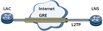
User Access in L2TP over GRE Scenarios
Generic Routing Encapsulation (GRE) is used to encapsulate packets of certain network layer protocols (such as IP, IPX, and AppleTalk) so that the encapsulated packets can be transmitted over the network on which another network layer protocol is applied. GRE provides a mechanism for encapsulating packets of one protocol into those of another protocol, allowing packets to be transmitted on heterogeneous networks. The channel for transmitting heterogeneous packets is called a tunnel.
In L2TP over GRE mode, the tunnel between the LAC and LNS is encapsulated into a GRE tunnel. Data packet transmission is the same as that in common L2TP access mode.