Traffic Shaping
What Is Traffic Shaping
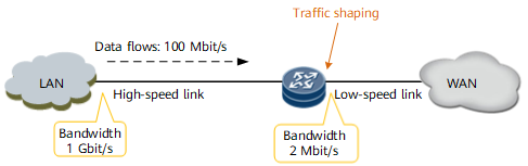
Traffic shaping controls the rate of outgoing packets to allow the traffic rate to match that on the downstream device. When traffic is transmitted from a high-speed link to a low-speed link or a traffic burst occurs, the inbound interface of the low-speed link is prone to severe data loss. To prevent this problem, traffic shaping must be configured on the outbound interface of the device connecting to the low-speed link, as shown in Figure 1.
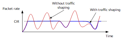
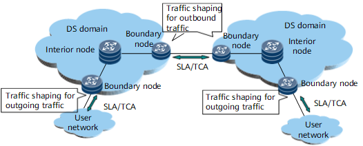
As shown in Figure 2, traffic shaping can be configured on the outbound interface of an upstream device to make irregular traffic transmitted at an even rate, preventing traffic congestion on the downstream device.
Traffic Shaping Implementation
Traffic shaping buffers overspeed packets and uses token buckets to transmit these packets afterward at an even rate.
On router, tokens are added at an interval, which is calculated in the format of CBS/CIR, with the quantity equal to the CBS for traffic shaping.

On router, the length of the frame header and CRC field are calculated in the bandwidth for packets to which CAR applies but not calculated in the bandwidth for packets that have been implemented with traffic shaping. For example, if the traffic shaping value is set to 23 Mbit/s for IPoE packets, the IP packets are transmitted at a rate of 23 Mbit/s with the lengths of the frame header and CRC field not counted.
In addition, whether the CBS can be modified in traffic shaping is determined by the product model, product version, and board type.
Traffic shaping is implemented for packets that have been implemented with queue scheduling and are leaving the queues. For details about queues and queue scheduling, see Congestion Management and Avoidance.
There are two traffic shaping modes: queue-based traffic shaping and interface-based traffic shaping.
- Queue-based traffic shaping applies to each queue on an outbound interface.
- When packets have been implemented with queue scheduling and are leaving queues, the packets that do not need traffic shaping are forwarded; the packets that need traffic shaping are measured against token buckets.
- After queues are measured against token buckets, if packets in a queue are transmitted at a rate conforming to the specifications, the packets in the queue are marked green and forwarded. If packets in a queue are transmitted at a rate exceeding the specifications, the packet that is leaving the queue is forwarded, but the queue is marked unscheduled and can be scheduled after new tokens are added to the token bucket. After the queue is marked unscheduled, more packets can be put into the queue, but excess packets over the queue capacity are dropped. Therefore, traffic shaping allows traffic to be sent at an even rate but does not provide a zero-packet-loss guarantee.
- Figure 3 Queue-based traffic shaping

- Assume that the CIR is set to 1 Mbit/s and CBS to 2000 bytes for traffic shaping for a queue, bucket C is initially full of tokens (to be specific, the depth of bucket C is 2000 bytes), and the number of tokens that are placed in the token bucket per millisecond is 125 bytes, which is calculated using the formula of 1 Mbit/s x 1 ms = 1000 bits = 125 bytes.
- If the first packet arriving at the interface is 1500 bytes long, the packet is marked green because the number of tokens in bucket C is greater than the packet length. The number of tokens in bucket C then decreases by 1500 bytes, with 500 bytes remaining.
- Assume that the second packet of 1500 bytes arrives at the interface 1 ms later. At this time, 125-byte tokens have been added to bucket C, and bucket C has a total of 625-byte tokens (with the remaining 500-byte tokens being included). As the number of tokens in the token bucket is greater than 0, the system forwards the packet, and the number of remaining tokens in the token bucket is -875 bytes (625 bytes - 1500 bytes). As the number of tokens in the token bucket becomes a minus, the system does not forward the packet.
- 1 ms later, the third packet of 1000 bytes arrives at the interface. At this time, the number of remaining tokens in bucket C is still a minus (-875 bytes + 125 bytes = -750 bytes). Therefore, the system does not forward packets.
- 6 ms later, the fourth packet of 1500 bytes arrives at the interface. At this time, the number of tokens in bucket C is 0 (-750 bytes + 125 bytes x 6 = 0). Therefore, the system does not forward packets.
- 1 ms later, the fifth packet of 1500 bytes arrives at the interface. At this time, bucket C has 125-byte tokens. Therefore, the system forwards the third packet. After that, the number of tokens in the token bucket becomes a minus again (125 bytes - 1000 bytes = -875 bytes). Therefore, the system does not forward packets.
The following table illustrates this process:Table 1 No.
Time
Packet Length
Tokens in Bucket C Before Packet Processing
Tokens in Bucket C After Packet Processing
Processing Result
Queue Status Before Packet Processing
Queue Status After Packet Processing
-
-
-
2000
2000
-
Schedulable
Schedulable
1
0
1500
2000
500
First packet being forwarded
Schedulable
Schedulable
2
First ms
1500
625
-875
Second packet being forwarded
Scheduling suspended
Scheduling suspended
3
Second ms
1000
-750
-750
Third packet being forwarded
Scheduling suspended
Scheduling suspended
4
Eighth ms
1500
0
0
Fourth packet being forwarded
Scheduling suspended
Scheduling suspended
5
Ninth ms
1500
125
-875
Third packet being forwarded
Schedulable
Scheduling suspended
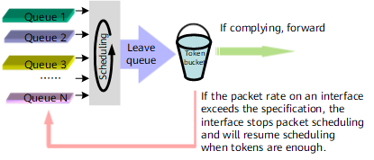
- Interface-based traffic shaping, also called line rate (LR), is used to restrict the rate at which all packets (including burst packets) are transmitted. Interface-based traffic shaping takes effect on the entire outbound interface, regardless of packet priorities. Figure 4 shows how interface-based traffic shaping is implemented:
- When packets have been implemented with queue scheduling and are leaving queues, all queues are measured together against token buckets.
- After queues are measured against token buckets, if the packets total-rate conforming to the specifications, the queue is forwarded. If the packet rate on an interface exceeds the specification, the interface stops packet scheduling and will resume scheduling when tokens are enough.
The principle of traffic shaping on an interface is the same as that of traffic shaping for queues and is not described here.
Traffic Shaping Applications
Traffic shaping controls the traffic output to minimize packet loss.
Interface-based traffic shaping
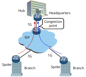
As shown in Figure 6, enterprise headquarters are connected to branches through leased lines on an ISP network in Hub-Spoke mode. The bandwidth of each leased line is 1 Gbit/s. If all branches send data to headquarters, traffic congestion occurs on the nodes connecting to headquarters at the ISP network edge. To prevent packet loss, configure traffic shaping on outbound interfaces of the nodes at the branch network edge.
Queue-based traffic shaping
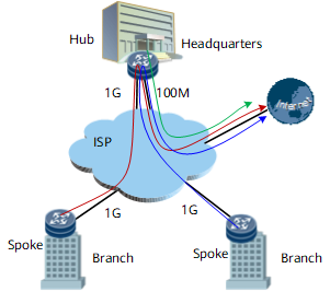
As shown in Figure 7, enterprise headquarters are connected to branches through leased lines on an ISP network in Hub-Spoke mode. The bandwidth of each leased line is 1 Gbit/s. Branches access the Internet through headquarters, but the link bandwidth between headquarters and the Internet is only 100 Mbit/s. If all branches access the Internet at a high rate, the rate of web traffic sent from headquarters to the Internet may exceed 100 Mbit/s, causing web packet loss on the ISP network.
To prevent web packet loss, configure queue-based traffic shaping for web traffic on outbound interfaces of branches and outbound interfaces connecting to the Internet on headquarters.
Shaped Rate Adjustment: Last-Mile QoS
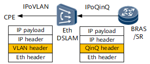
Last mile indicates the link between the user and the access switch (such as the Ethernet DSLAM), as shown in Figure 8. Residential and enterprise users generally access the Ethernet DSLAM using IPoE, PPPoE and the DSLAM is connected to the BRAS or SR, edge device on the backbone network, through a metropolitan area network (MAN).
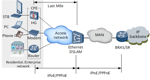
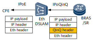
In a broadband service access scenario, an Ethernet link connects a BRAS or SR and a DSLAM. The BRAS or SR encapsulates Ethernet packets, and traffic shaping is implemented based on the Ethernet packets.
Even if the link connects the user and DSLAM is also an Ethernet link, the encapsulation cost of the packets sent between the user and DSLAM can possibly exceed that on the user side of the BRAS or SR. For example, the Ethernet packet encapsulated on the BRAS or SR does not carry a VLAN tag, but the packet sent between the user and DSLAM carries a single or double VLAN tags due to VLAN or QinQ encapsulation.
To resolve this problem, last-mile QoS can be configured on the BRAS or SR. Last-mile QoS allows a device to calculate the length of headers to be added to packets based on the bandwidth purchased by users and the bandwidth of the downstream interface on the DSLAM for traffic shaping.
Therefore, the BRAS or SR cannot automatically infer the sum length of the packets that has been encapsulated on the DSLAM and requires compensation bytes.
After compensation bytes are configured, if the DSLAM connects to the CPE through an Ethernet link, the BRAS or SR can automatically infer the sum length of the packet encapsulated on the DSLAM based on the length of the forwarded packet and the configured compensation bytes, and determine the shaped rate to be adjusted.
The following tables provide common encapsulation-costs and compensation bytes.
Encapsulation Type |
Encapsulation-cost (Bytes) |
|
|---|---|---|
Eth header |
14 |
|
VLAN header |
4 |
|
QinQ header |
8 |
|
AAL5 encapsulation |
VC |
AAL5 Header + AAL5 tail = 0 + 8 = 8 |
LLC Type1 (connection-less mode, such as IPoE, PPPoE) |
AAL5 Header + AAL5 tail = 8 + 8 = 16 |
|
Scenario |
Compensation Bytes |
|---|---|
|
= VLAN header - QinQ header = - 4 |
|
= 0 - QinQ header = - 8 |