Understanding MPLS HQoS
QoS Resource Verification After the PW Bandwidth Is Configured (L2VPN)
The tunnel to which a PW is to recurse must meet specific requirements. The tunnel bandwidth must be higher than the PW bandwidth. In addition, the SQ resources of the tunnel must meet the HQoS hardware resource requirements.
The tunnel to which a PW is to recurse may vary after the PW bandwidth is configured. If the PW bandwidth does not meet specific requirements or the SQ resources are insufficient, the PW may fail to recurse to the tunnel and becomes Down.
Implementing HQoS (L2VPN) at the Public Network Side Based on VPN + Peer PE
In the MPLS VPN, bandwidth agreement may need to be reached between PE devices of an operator, so that traffic between two PEs is restricted or guaranteed according to the bandwidth agreement. To achieve this end, HQoS at the public network side that is based on VPN + Peer PE can be adopted.
As shown in Figure 1, bandwidth and class of service are specified for traffic between PEs at the MPLS VPN side. For example, in VLL 1, the specified bandwidth for traffic between PE1 and PE2 is 30 Mbit/s, and higher priority services are given bandwidth ahead of lower priority services.

If, however, you need to implement bandwidth restriction rather than bandwidth guarantee at the network side, you can simply specify the CIR to be 0, and the PIR to the desired bandwidth.
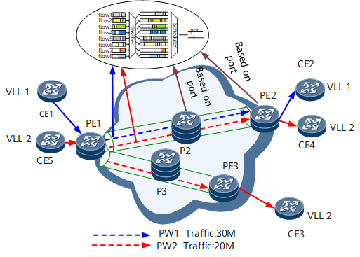
The preceding traffic model is described as follows:
In this scenario, the LDP tunnel or the TE tunnel that is not allocated bandwidth is adopted.
QoS is configured based on VLL + peer PE to implement bandwidth restriction at the network side.
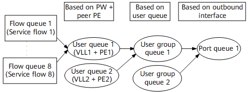
As shown in Figure 2, at the egress PE, traffic is mapped to eight flow queues in the service queue (SQ) according to the preference information carried by the traffic. Flow queues belonging to the same VLL + peer PE are mapped to the same SQ (namely, for traffic destination PE from VLLs is PE2, one queue among the eight queues is mapped; for traffic destination PE from VLLs is PE3, the other queue is mapped).
Based on the user's requirements, multiple VLLs + peer PEs can be configured to be in one user group, and undergo group queue (GQ) scheduling.
On the outbound interface, traffic first undergoes port queue scheduling, and is then forwarded.
In this scenario, priority scheduling of flow queues is supported, bandwidth restriction and bandwidth guarantee of SQs are supported, whereas only traffic shaping is supported for GQs.
In this scenario, the TE tunnel that is allocated bandwidth is adopted.
Scenario 2 differs from scenario 1 in the following aspects.
After traffic undergoes the SQ scheduling, by default, traffic undergoes GQ scheduling that is based on the TE tunnel. That is, by default, all traffic in one TE tunnel is regarded as being in one GQ. GQ scheduling, however, can also be configured to be based on VLL + peer PE according to the user's requirements. In this case, the default GQ scheduling that is based on the TE tunnel is no longer effective.
PE-to-PE bandwidth guarantee for traffic is supported. This is because in this scenario, bandwidth resources are reserved for the TE tunnel.
If traffic is load-balanced among TE tunnels on peer PEs, all traffic that is load-balanced undergoes priority scheduling and bandwidth restriction according to the traffic scheduling procedure as shown in Figure 3.
In this scenario, it is recommended that the TE tunnel that is configured with bandwidth resources be adopted to achieve PE-to-PE bandwidth guarantee for traffic.

Implementing VPN-based Traffic Statistics
In a VPLS or VPWS network, the PE device supports statistics on both the incoming and outgoing traffic at the AC or PW side (at the AC side, traffic statistics are based on the interface, whereas at the PW side, traffic statistics are based on the PW table). After MPLS HQoS is configured, traffic statistics can be produced on packets at the PW side that are sent based on their priorities.
In an L3VPN, the PE device supports statistics on both the incoming and outgoing traffic of the VPN user (based on interfaces at the VPN side). After MPLS HQoS is configured, traffic statistics can be produced on packets at the public network side of the ingress PE that are sent based on their priorities.
In a VLL or VSI, the PE device supports statistics on both the incoming and outgoing traffic of the VLL or VSI user (based on interfaces at the VPN side). After MPLS HQoS is configured, traffic statistics can be produced on packets at the public network side of the ingress PE that are sent based on their priorities.