MPLS L3VPN Scenario
MPLS L3VPN Typical Topology
Figure 1 MPLS L3VPN typical topology
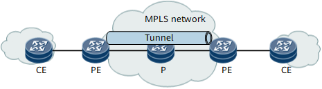
- PE (provider edge): an edge device on the provider network, which is directly connected to the CE. The PE receives traffic from the CE and then encapsulates the traffic with MPLS header, and then sends the traffic to P. The PE also receives traffic from the P and then remove the MPLS header from the traffic, and then sends the traffic to CE.
- P (Provider): a backbone device on the provider network, which is not directly connected to the CE. Ps perform basic MPLS forwarding.
- CE (customer edge): an edge device on the private network.
Suitable Scenario 1: Load Balance on Ingress PE of L3VPN
Figure 2 Route load balance on ingress PE
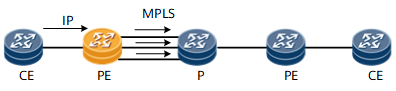
Figure 3 Trunk load balance on ingress PE
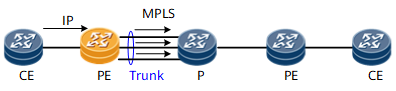
Figure 4 Tunnel load balance on ingress PE
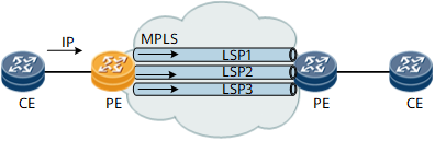
The hash algorithm is performed based on the packet format of the inbound traffic from AC interface. The hash factors can be IP 5-tuple or IP 2-tuple. The result of the load balancing depends on the discreteness of the private IP addresses or TCP/UDP ports of the packets.
Suitable Scenario 2: Load Balance on P Node
Figure 5 Route load balance on P
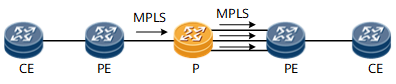
Figure 6 Trunk load balance on P
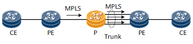
The hash algorithm on P node is performed based on the packet
format of the inbound MPLS traffic.
- If the number of MPLS labels in the packet is less than four, the hash factors can be IP 5-tuple or IP 2-tuple. The result of the load balancing depends on the discreteness of the private IP addresses or TCP/UDP ports of the packets.
- In the complex scenarios such as inter-AS VPN, FRR and LDP over TE, the number of the labels in the packet may be four or more. In these scenarios, the hash factors are the layer 4 or layer 5 label. The result of the load balancing depends on the discreteness of the layer 4 or layer 5 labels of the packets.
Suitable Scenario 3: Load Balance on Egress PE of L3VPN
Figure 7 Route load balance on egress PE
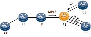
Figure 8 Trunk load balance on egress PE

The hash algorithm of the load balance on egress PE is the same as Scenario 2 if the Penultimate Hop Popping (PHP) is disabled, the same as Scenario 1 if the Penultimate Hop Popping (PHP) is enabled.
Suitable Scenario 4: Load Balancing Among the L3 Outbound Interfaces in the Access of L2VPN to L3VPN Scenarios
Figure 9 Load Balancing Among the L3 Outbound Interfaces in the Access
of L2VPN to L3VPN Scenarios
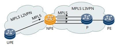
In access of L2VPN to L3VPN scenarios, the hash algorithm is the same as Scenario 1.