Segment Routing Load Balancing
SR-MPLS TE Load Balancing
SR-MPLS TE guides data packet forwarding based on the label stack information encapsulated by the ingress into data packets. By default, each adjacency label identifies a specific adjacency, meaning that load balancing cannot be performed even if equal-cost links exist. To address this issue, SR-MPLS TE uses parallel adjacency labels to identify multiple equal-cost links.
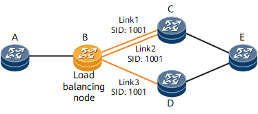
In Figure 1, there are three equal-cost links from nodes B to E. Adjacency SIDs with the same value, such as 1001 in Figure 1, can be configured for the links. Such SIDs are called parallel adjacency labels, which are also used for path computation like common adjacency labels.
When receiving data packets carrying parallel adjacency labels, node B parses the labels and uses the hash algorithm to load-balance the traffic over the three equal-cost links, improving network resource utilization and avoiding network congestion.
Configuring parallel adjacency labels does not affect the allocation of common adjacency labels between IGP neighbors. After parallel adjacency labels are configured, the involved device advertises multiple adjacency labels for the same adjacency.
If BFD for SR-MPLS TE is enabled and SR-MPLS TE parallel adjacency labels are used, BFD packets can be load-balanced, whereas each BFD packet is hashed to a single link. If the link fails, BFD may detect a link-down event even if the other links keep working properly. As a result, a false alarm may be reported.
SR-MPLS TE Policy Load Balancing
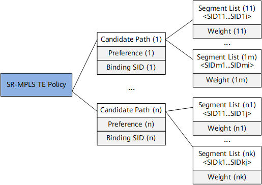
Figure 2shows the SR-MPLS TE Policy model. One SR-MPLS TE Policy may contain multiple candidate paths with Preference and Binding SID attributes. The valid candidate path with the highest preference functions as the primary path of the SR-MPLS TE Policy, and the valid candidate path with the second highest preference functions as the hot-standby path.
A candidate path can contain multiple segment lists, each of which carries the Weight attribute. Currently, this attribute cannot be set and is defaulted to 1. A segment list is an explicit label stack that instructs a network device to forward packets. Multiple segment lists can work in load balancing mode.
BGP EPE Load Balancing
BGP EPE allocates BGP peer SIDs to inter-AS paths. BGP-LS advertises the BGP peer SIDs to the network controller. If a forwarder does not establish a BGP-LS peer relationship with the controller, the forwarder runs BGP-LS to advertise a peer SID to a BGP peer that establishes a BGP-LSP peer relationship with the controller. The BGP peer then runs BGP-LS to advertise the peer SID to the network controller. In Figure 3, BGP EPE allocates the peer node segment (peer-node SID), peer adjacency segment (peer-Adj SID) and peer-set SID to peers.
A peer-set SID identifies a group of peers that are planned as a set. BGP allocates a peer-set SID to the set. Each peer-set SID can map multiple outbound interfaces during forwarding. Because one peer set consists of multiple peer nodes and peer adjacencies, the SID allocated to a peer set maps multiple peer-node SIDs and peer-Adj SIDs.

On the network shown in Figure 3, ASBR1 and ASBR3 are directly connected through two physical links. An EBGP peer relationship is established between ASBR1 and ASBR3 through loopback interfaces. ASBR1 runs BGP EPE to assign the Peer-Node SID 28001 to its peer (ASBR3) and to assign the Peer-Adj SIDs 18001 and 18002 to the physical links. For an EBGP peer relationship established between directly connected physical interfaces, BGP EPE allocates a Peer-Node SID rather than a Peer-Adj SID. For example, on the network shown in Figure 3, BGP EPE allocates only Peer-Node SIDs 28002, 28003, and 28004 to the ASBR1-ASBR5, ARBR2-ASBR4, and ASBR2-ASBR5 peer relationships, respectively.