Instructions on How to Use an Optical Module
This section describes instructions on how to use an optical module.

Only optical modules matching Huawei products can be used. These optical modules are strictly tested by Huawei. If non-matching optical modules are used, device requirements may fail to be met, and services may fail to run properly. To replace optical modules, see Parts Replacement-Replacing an Optical Module.
ESD Measures
Before touching any optical module, wear an ESD wrist strap or ESD gloves. Take full ESD measures when installing optical apparatus such as optical modules indoors or outdoors.


Placing Optical Apparatus and fibers
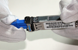
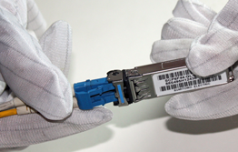
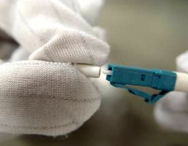
Do not touch pins or connecting fingers with bare hands. Handle the optical fibers gently. Use two fingers to hold the fiber connector instead of grasping the fiber or the fiber cover.
Do not apply axial or lateral fiber wallop bumps on the fiber. Do not fold, twist, or crush the tail fiber. Do not drag the tail fiber or press the coupling point of the tail fiber. Figure 3 shows how to properly place optical apparatus and fibers.

Install the fiber in circles with diameter longer than 6 cm ( 0.20 ft ).
Uninstalling Optical Apparatus
Open the buckle and slowly take out the optical apparatus. Do not drag the optical fiber to forcibly take out the optical fiber. Ensure that the optical fiber is connected to and removed from the interface horizontally.
Figure 4 The tab is closed Figure 5 The tab is open
155Mbps SFP Electrical Transceiver, in Figure 6 (1) shows a black plastic latch. Press the latch to unlock the electrical module. As (2) indicates, hold the two sides of the electrical module to remove it.
Please do not remove the black plastic latch when removing the electrical module.

If the black plastic latch falls off, use an auxiliary tool, such as a pair of tweezers, to press the cage buckle, as shown in the following figure. Then, hold the two sides of the electrical module to remove it.

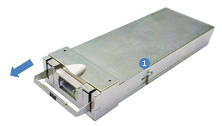
CFP2 optical module(02311LYG), in Figure 7, Push the puller to the bottom until the latch shown in (1) automatically unlocks the optical module. Then, horizontally drag the puller to remove the optical module.
When removing a CFP optical module, loosen the two screw rods of the module and then remove the module slowly. Do not directly drag the optical fiber to pull out the optical module or forcibly pull out the optical module.


The QSFP28 and QSFP-DD modules will get very hot during operation. To prevent injuries, do not touch the module shells when removing the modules.

Precautions for the loosened optical module
When installing an optical module, force it into position. If a crack sound is heard or a slight tremor is felt, it indicates that the latch boss is secured. When the latch boss is not secured, the connecting finger is unstably connected to the connector on the board, and the link may become Up. On the condition that the optical module tremors or collides with another object, however, the optical module will be loosened or the optical signals will be temporarily cut off.
When inserting the optical module, make sure that the tab is closed. (At this time, the latch boss locks the optical module.) After the optical module is inserted, try pulling it out to see if it is installed in position. If the optical module cannot be pulled out, it is secured.
If you cannot push the optical module into an optical module cage any longer, the optical module is in good contact with the board connector.
When installing a CFP optical module, push the module panel horizontally into the connector using even force with both thumbs. After the module is inserted, push the module slightly to ensure that it has reached the stop position.
After the CFP optical module is securely inserted, tighten the two screw rods of the module alternately. To prevent the module from getting loosened due to vibration or collision, you are advised to use a screwdriver to tighten the screw rods.
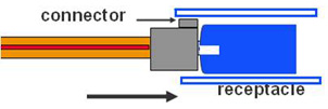
Precautions for receptacle contamination
Clean tissues must be prepared for deployment on site. You need to clean the optical connector before inserting it in the receptacle. This protects the receptacle against the contamination.
Use at least three cleaning tissues. Wipe the end of an optical connector horizontally in one direction, and then move the connector end to the unused part of the cleaning tissue to continue. Generally, one cleaning tissue is used for cleaning an optical connector.
To prevent contamination, the optical module should be covered with either a dust cap or an optical connector.
Cover an optical module with a dust cap.
Cover an optical module with an optical connector
Lay the optical fibers on the Optical-fiber Distribution Frame (ODF) or coil them up in a fiber management tray. Make sure that the optical fibers are not squeezed.
If a receptacle or an optical connector has not been used for a long time and has not been covered with a dust cap, you should clean it before using it. A cotton swab is used to clean a receptacle, and a cleaning tissue is used to clean an optical connector.
During the cleaning process, insert the cotton swab and turn it slowly in the receptacle. Do not use too much force, because the receptacle may be damaged.

If, for no apparent reason, optical signals are lost during the operation of a device, use the preceding method to clean the receptacle or the optical connector. This will eliminate contamination as the cause of the signal loss.
Precautions for the overload-caused burnt optical module
When using an OTDR to test the connectivity or the attenuation of optical signals, disconnect the optical connector from the optical module. Otherwise, the optical module may be burnt.
When performing a self-loop test, use an optical attenuator. Do not loosen the optical connector.
It is required that a long-distance optical module have an input optical power of less than -7 dBm. If the input optical power is larger than -7 dBm, you need to add an optical attenuator. For example, if the transmitting optical power is X dBm and the optical attenuation is Y dB, the receiving optical power is X-Y, which must be smaller than -7dBm (X-Y<-7 dBm).
Inspecting Optical Fiber Connectors
The Ethernet port rate is increasing and the quality requirement for optical fibers and optical cables is higher. Table 1 describes requirements for the loss of optical fiber connectors according to the national standard (GBT50312-2016).
Type |
Maximum attenuation of an optical fiber connector (dB) |
|---|---|
Fiber splicing connector |
0.3 |
Optical mechanical connector |
0.3 |
Optical connector |
0.75 |
Fiber cores are connected through connectors, such as the ODF, optical attenuator, and flange, in splicing and mechanical modes.
Table 2 describes requirements for the reflection of the optical fiber connector when Ethernet ports (such as 200G and 50G) use PAM4 encoding to double the rate. More connectors bring lower requirements for the reflection.
Number of Optical Fiber Connectors |
Maximum Reflection of Each Connector (dB) |
|---|---|
1 |
-22 |
2 |
-29 |
4 |
-33 |
6 |
-35 |
8 |
-37 |
10 |
-39 |
Link splice loss and reflectance values of the test methods and the following processing steps:
After the optical fiber at the peer end is disconnected, use the OTDR meter to test the local end. Check whether the loss and reflection of each link and node are normal. (The loss of a fiber splicing connector should be less than 0.3 dB, the loss of a connector should be less than 0.75 dB, and the reflection of a connector should be less than -30 dB.) If the test result is not within the required range, process the abnormal port.
Locate the equipment room where the port resides based on the distance between abnormal points in the OTDR test result. Preliminarily determine the port location, disconnect the port, and perform an OTDR test on the port that reports alarms. Check whether the distance is consistent with that in the previous test. If not, continue to test other ports.
After the abnormal port is found, test the port using a fiber microscope. If the port is dirty, clean it.
After the port is cleaned, restore the port, and ensure that the connector is tightened. Perform an OTDR test on the port to check whether loss and reflection of each link and node are normal.
If the fault persists, replace the flange and perform an OTDR test on the port that reports alarms to check whether loss and reflection of each link and node are normal.
If the fault persists, replace the optical fiber and perform an OTDR test on the port that reports alarms to check whether loss and reflection of each link and node are normal.
If multiple abnormal points exist on the link, repeat steps 2 to 6.
Other precautions
The optical connector should be horizontally inserted in the receptacle to avoid damages to the receptacle.
Mixed use of multi-mode and single-mode optical fibers is prohibited. Otherwise, faults such as signal loss may occur.
Method of distinguishing optical modules in single mode and multi-mode.
Table 3 Method of distinguishing optical modules in single mode and multi-mode Item
Single mode
Multi-mode
Transmission distance
10 km or longer
Below 0.5 km
Wavelength
Non-850 nm
850 nm
Information on the label
SM
MM
50G Optical Module Installation Guide
1. Precautions for optical module installation
(1) If a cabinet with a door is used, a sufficient distance must be reserved between the optical module and the cabinet door to prevent the puller or patch cord from bumping on the door.
(2) Long-distance optical modules must be equipped with optical attenuators for self-loops. For a 50GBase-ER (40 km) long-distance optical module, the receive optical power damage threshold is lower than the average minimum transmit optical power, making the module prone to damage caused by self-loops. Therefore, the module must be equipped with an optical attenuator for self-loops.
(3) When optical path quality is tested using an OTDR, optical fibers must be removed from the associated optical module. This is because the OTDR's transmit optical power is far greater than the optical power damage threshold at the receive end of an optical module.
2. Method of checking an optical path

3. Method of cleaning the end faces of an optical fiber
Before cleaning the end faces of an optical fiber that is in use, ensure that the optical fiber has no optical signals. To achieve this, shut down the ports at both ends of the fiber. Then, clean the end faces and insert the optical fiber back into the corresponding port.
To clean the end faces of an optical fiber that is not in use, remove the dust-proof cap from the fiber connector (or the patch cord connector of the involved optical component), and put the dust-proof cap into a dedicated cleaning kit. After the cleaning is complete, re-install the dust-proof cap.
- Use the untouched part of a lint-free wipe to wipe the connector end face along one direction.
- If the end face of an optical fiber cannot be cleaned due to serious contamination, use a lint-free wipe dipped with cleanser to wipe the end face along one direction. Then, use a dry lint-free wipe to clean the end face. Ensure that the end face is dry before using the optical fiber.
- After the cleaning is complete, immediately install a dust-proof cap for any optical fiber connector that is not in use.
4. Precautions for using a lint-free wipe to clean the end face of an optical fiber
- Use a smooth surface of the lint-free wipe for cleaning.
- Ensure that the optical fiber connector is vertical to the lint-free wipe during cleaning.
- Wipe the end face along the direction of the lint-free wipe's grain.
- Wipe the end face along one direction only.
- Any part of a lint-free wipe can be used only once, and a small piece of lint-free wipe can be used to clean only one connector.
5. Method of using lint-free swabs to clean the optical port of an optical module
Remove the dust-proof cap from the optical port of the optical module, and put the dust-proof cap into a dedicated cleaning kit.
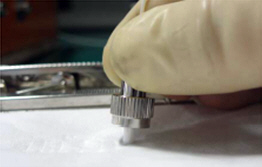
- Select a proper lint-free swab based on the type of the optical port to be cleaned. (For SC optical ports, use lint-free swabs with a diameter of 2.5 mm; for LC and MTRJ optical ports, use lint-free swabs with a diameter of 1.25 mm.) Dip the lint-free swab into cleanser, insert it into the inside of the optical port, and clean the optical port by rotating the swab 360 degrees in one direction along the inner wall of the optical port.
- Insert a dry lint-free swab of the same type into the inside of the optical port and clean the optical port by rotating the swab 360 degrees in one direction along the inner wall of the optical port.
- Cap the optical port after the cleaning is complete.
6. Precautions for using lint-free swabs to clean the optical port of an optical module
- When cleaning the optical port of an optical module, clean the end faces of associated optical fibers to prevent the optical fibers from dirtying the optical port.
- In general, each lint-free swab can be used for cleaning only once. If a used lint-free swab is confirmed clean and can be reused, it can be used for a maximum of three times. For example, a lint-free swab that is ever used to dry an optical port can be used for a maximum of three times.
7. Safety precautions
- Electrostatic protection: Active optical and electrical components are extremely sensitive to electrostatic. Therefore, take strict measures to protect against electrostatic. For example, wear ESD gloves during operations and touch only the shell of the involved component.
- Laser protection: Do not look into optical ports without eye protection when reseating a module.
8. Discrete reflectance
Focus on the reflection indicators of each node during link deployment. The discrete reflection indicators must meet the IEEE standards.
Number of discrete reflectances greater than –55 dB |
QSFP28 50G-FR (Maximum value of each discrete reflectance) |
QSFP28 50G-LR (Maximum value of each discrete reflectance) |
QSFP28 50G-ER (Maximum value of each discrete reflectance) |
|---|---|---|---|
1 |
-25 dB |
-22 dB |
-19 dB |
2 |
-31 dB |
-29 dB |
-27 dB |
4 |
-35 dB |
-33 dB |
-32 dB |
6 |
-38 dB |
-35 dB |
-35 dB |
8 |
-40 dB |
-37 dB |
-37 dB |
10 |
-41 dB |
-39 dB |
-39 dB |