10-Port-MPO-12-40-Port-LC-Breakout Box(single-mode)
Appearance

Components

1. MPO adapter |
2. LC adapter |
3. Mounting ear |
MPO adapters map LC adapters according to their numbers displayed on the panel. Figure 3 shows the mapping between MPO and LC adapters.

MPO-12 Jumper
The TYPE-B MPO jumper is used. The following figure shows the MPO-12 jumper structure and line orders of X1 and X2 ports.
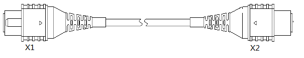
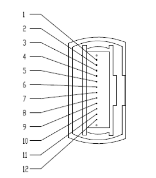
Table 1 describes the mappings between the lanes of the X1 and X2 ports.
Technical Specifications
Item |
Description |
|---|---|
BOM Number |
02082890 |
Official Name |
ODBS10040 |
Dimensions (H x W x D) |
43.6 mm x 442 mm x 164 mm |
Mounting ear |
19-inch supported |
Weight |
2.3 kg |
Insertion loss |
≤ 0.75 db |
Return loss |
Single-mode: ≥ 30 db |
Operating temperature |
–40°C to +65°C |
Storage temperature |
–40°C to +70°C |
Relative operating humidity |
|
Relative storage humidity |
0% RH to 95% RH, non-condensing |
Optical Module |
MPO-MPO Fiber |
Port |
|---|---|---|
[02311NUA/OSM010N11] Function Module,OSM010N11,High Speed Transceiver,QSFP+,1310,41.25Gbps,-8.2dBm,0.5dBm,-12.6dBm,MPO,SM,10km |
[14134759/MPO12-MPO12-SM-10] Optical Cable Parts,MPO/APC,MPO/APC,Single mode,10m,8 cores,GJFH-8G.657A2,3.5mm,LSZH,43mm Short MPO,Bending insensitive |
Supported boards: Check the Hardware Description. If the description of a port contains QSFP28 or QSFP+ and and supports the breakout function, the optical module and breakout fiber can be used together with the port. |