Example for Configuring Static BFD for TE with Automatically Negotiated Discriminators
Static BFD for TE is configured to rapidly detect tunnel faults and perform a traffic switchover.
Networking Requirements
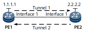
On the MPLS network shown in Figure 1, MPLS TE tunnels are established between PE1 and PE2. The tunnels are detected using static BFD sessions with automatically negotiated discriminators.

Configuration Roadmap
The configuration roadmap is as follows:
Configure an MPLS network and establish bidirectional TE tunnels between PE1 and PE2.
Enable BFD globally on PE1 and PE2.
Configure static BFD with automatically negotiated discriminators on PE1 and PE2 to monitor TE tunnels.
Data Preparation
To complete the configuration, you need the following data:
MPLS LSR IDs
Interface number of and bandwidth consumed by each tunnel, and name of an explicit path over which each tunnel is established
Name of a BFD session
Procedure
- Assign an IP address to each interface.
Assign an IP address to each interface according to Figure 1, create loopback interfaces on routers, and configure the IP addresses of the loopback interfaces as MPLS LSR IDs. For configuration details, see Configuration Files in this section.
- Configure an IGP.
Configure OSPF or IS-IS on each router to ensure interworking between PE1 and PE2. OSPF is used in the example. For configuration details, see Configuration Files in this section.
- Configure basic MPLS TE functions.
On each router, configure an LSR ID and enable MPLS in the system and interface views. For configuration details, see Configuration Files in this section.
- Configure basic MPLS TE functions.
On each router, enable MPLS-TE in the MPLS and interface views. For configuration details, see Configuration Files in this section.
- Enable OSPF TE and configure CSPF.
Enable OSPF TE on each router and configure CSPF on PE1. For configuration details, see Configuration Files in this section.
- Configure a tunnel interface on each PE.
# Configure PE1.
[*PE1] interface tunnel 1
[*PE1-Tunnel1] ip address unnumbered interface loopback 0
[*PE1-Tunnel1] tunnel-protocol mpls te
[*PE1-Tunnel1] destination 2.2.2.2
[*PE1-Tunnel1] mpls te tunnel-id 1
[*PE1-Tunnel1] commit
[~PE1-Tunnel1] quit
# Configure PE2.
[~PE2] interface tunnel 2
[*PE2-Tunnel2] ip address unnumbered interface loopback 0
[*PE2-Tunnel2] tunnel-protocol mpls te
[*PE2-Tunnel2] destination 1.1.1.1
[*PE2-Tunnel2] mpls te tunnel-id 2
[*PE2-Tunnel2] commit
[~PE2-Tunnel2] quit
- Configure static BFD with automatically negotiated discriminators to detect TE tunnel faults.
# Configure PE1.
[*PE1] bfd aaa bind mpls-te interface Tunnel1 reverse-te lsr-id 2.2.2.2 tunnel-id 2 auto# Configure PE2.
[*PE2] bfd bbb bind mpls-te interface Tunnel2 reverse-te lsr-id 1.1.1.1 tunnel-id 1 auto - Verify the configuration.
After completing the preceding configuration, run the display bfd session all command on PE2 to view information about the configured BFD session.
[*PE2]display bfd session all
(w): State in WTR
(*): State is invalid
--------------------------------------------------------------------------------
Local      Remote     PeerIpAddr      State     Type        InterfaceName
--------------------------------------------------------------------------------
1638       16385       1.1.1.1         UP      AUTO_TE_TNL    Tunnel0/0/2
--------------------------------------------------------------------------------
Configuration Files
PE1 configuration file
#
 sysname PE1
#
 bfd
#
 mpls lsr-id 1.1.1.1
 mpls
  mpls te
  mpls rsvp-te
  mpls te cspf
#
interface gigabitethernet0/1/1
 undo shutdown
 ip address 10.1.1.1 255.255.255.0
 mpls
 mpls te
 mpls rsvp-te
#
interface LoopBack0
 ip address 1.1.1.1 255.255.255.255
#
interface Tunnel1
 ip address unnumbered interface LoopBack1
 tunnel-protocol mpls te
 destination 2.2.2.2
 mpls te tunnel-id 1
#
ospf 1
 opaque-capability enable
 area 0.0.0.0
  network 1.1.1.1 0.0.0.0
  network 10.1.1.0 0.0.0.255
  mpls-te enable
#
bfd aaa bind mpls-te interface Tunnel1 reverse-te lsr-id 2.2.2.2 tunnel-id 2 auto
#
return
PE2 configuration file
#
 sysname PE2
#
 bfd
#
 mpls lsr-id 3.3.3.3
 mpls
  mpls te
  mpls rsvp-te
  mpls te cspf
#
interface gigabitethernet0/1/1
 undo shutdown
 ip address 10.2.1.2 255.255.255.0
 mpls
 mpls te
 mpls rsvp-te
#
interface LoopBack0
 ip address 2.2.2.2 255.255.255.255
#
interface Tunnel2
 ip address unnumbered interface LoopBack1
 tunnel-protocol mpls te
 destination 1.1.1.1
 mpls te tunnel-id 2
#
ospf 1
 opaque-capability enable
 area 0.0.0.0
  network 2.2.2.2 0.0.0.0
  network 10.1.1.0 0.0.0.255
  mpls-te enable
#
bfd bbb bind mpls-te interface Tunnel reverse-te lsr-id 1.1.1.1 tunnel-id 1 auto
#
return