BFD for TE CR-LSP
BFD for TE is an end-to-end rapid detection mechanism used to rapidly detect faults in the link of an MPLS TE tunnel. BFD for TE supports BFD for TE tunnel and BFD for TE CR-LSP. This section describes BFD for TE CR-LSP only.
Traditional detection mechanisms, such as RSVP Hello and Srefresh, detect faults slowly. BFD rapidly sends and receives packets to detect faults in a tunnel. If a fault occurs, BFD triggers a traffic switchover to protect traffic.
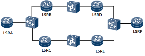
On the network shown in Figure 1, without BFD, if LSRE is faulty, LSRA and LSRF cannot immediately detect the fault due to the existence of Layer 2 switches, and the Hello mechanism will be used for fault detection. However, Hello mechanism-based fault detection is time-consuming.
To address these issues, BFD can be deployed. With BFD, if LSRE fails, LSRA and LSRF can detect the fault in a short time, and traffic can be rapidly switched to the path LSRA -> LSRB -> LSRD -> LSRF.
BFD for TE can quickly detect faults on CR-LSPs. After detecting a fault on a CR-LSP, BFD immediately notifies the forwarding plane of the fault to rapidly trigger a traffic switchover. BFD for TE is usually used together with the hot-standby CR-LSP mechanism.
A BFD session is bound to a CR-LSP and established between the ingress and egress. A BFD packet is sent by the ingress to the egress along the CR-LSP. Upon receipt, the egress responds to the BFD packet. The ingress can rapidly monitor the link status of the CR-LSP based on whether a reply packet is received.
After detecting a link fault, BFD reports the fault to the forwarding module. The forwarding module searches for a backup CR-LSP and switches service traffic to the backup CR-LSP. The forwarding module then reports the fault to the control plane.
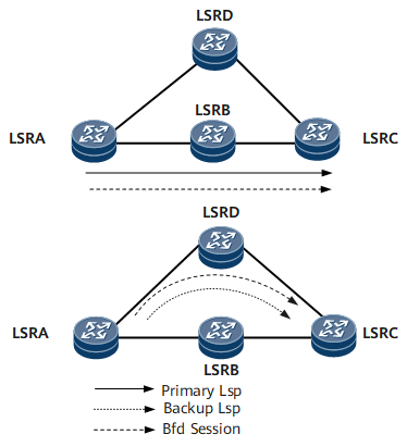
On the network shown in Figure 2, a BFD session is set up to detect faults on the link of the primary LSP. If a fault occurs on this link, the BFD session on the ingress immediately notifies the forwarding plane of the fault. The ingress switches traffic to the backup CR-LSP and sets up a new BFD session to detect faults on the link of the backup CR-LSP.
BFD for TE Deployment
The networking shown in Figure 3 applies to both BFD for TE CR-LSP and BFD for hot-standby CR-LSP.
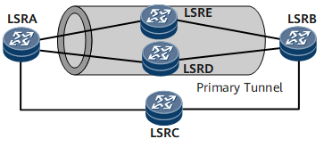
On the network shown in Figure 3, a primary CR-LSP is established along the path LSRA -> LSRB, and a hot-standby CR-LSP is configured. A BFD session is set up between LSRA and LSRB to detect faults on the link of the primary CR-LSP. If a fault occurs on the link of the primary CR-LSP, the BFD session rapidly notifies LSRA of the fault. After receiving the fault information, LSRA rapidly switches traffic to the hot-standby CR-LSP to ensure traffic continuity.