Example for Configuring a BGP SR LSP
Deploying a complete BGP SR LSP on devices in the same AS helps implement end-to-end service interworking.
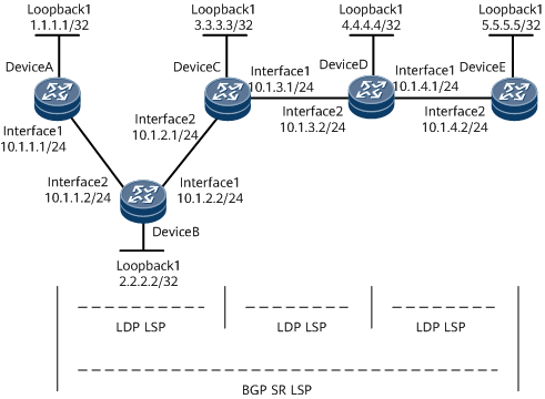
Networking Requirements
On the network shown in Figure 1, OSPF runs between DeviceA and DeviceB, between DeviceB and DeviceC, and between DeviceD and DeviceE. IS-IS runs between DeviceC and DeviceD. Basic MPLS functions and MPLS LDP are configured on DeviceA through DeviceE so that LDP LSPs are established between loopback interfaces of devices in each IGP area. In this case, traffic between loopback interfaces of devices in each IGP area is encapsulated using MPLS. However, traffic cannot be transmitted across IGP areas because devices cannot ping each other across IGP areas. For example, DeviceA cannot ping DeviceE. To solve this problem, you need to configure an inner MPLS tunnel (BGP SR LSP) from 1.1.1.1 to 5.5.5.5 so that the traffic from 1.1.1.1 to 5.5.5.5 is forwarded through MPLS.

In this example, interface1 and interface2 represent GE0/1/0 and GE0/1/8, respectively.
Configuration Roadmap
The configuration roadmap is as follows:
Configure IP addresses for interfaces.
Configure IGP areas.
Configure basic MPLS functions and MPLS LDP.
Configure a BGP SR LSP.
Data Preparation
To complete the configuration, you need the following data:
- MPLS LSR IDs of DeviceA through DeviceE
- SRGBs of DeviceA through DeviceE
Procedure
- Configure interface IP addresses.
Take DeviceA as an example.
<DeviceA> system-view
[~DeviceA] interface gigabitethernet 0/1/0
[~DeviceA-GigabitEthernet0/1/0] ip address 10.1.1.1 24
[*DeviceA-GigabitEthernet0/1/0] quit
[*DeviceA] interface loopBack 1
[*DeviceA-LoopBack1] ip address 1.1.1.1 32
[*DeviceA-LoopBack1] commit
[~DeviceA-LoopBack1] quit
The interfaces that directly connect the devices can ping each other, but the devices cannot ping each other's loopback interface.
- Deploy DeviceA through DeviceC in the same IGP area, and configure OSPF on them to implement interworking in the IGP area.
Take DeviceA as an example:
[~DeviceA] ospf 1 router-id 1.1.1.1
[~DeviceA-ospf-1] area 0
[*DeviceA-ospf-1-area-0.0.0.0] network 1.1.1.1 0.0.0.0
[*DeviceA-ospf-1-area-0.0.0.0] network 10.1.1.0 0.0.0.255
[*DeviceA-ospf-1-area-0.0.0.0] commit
[~DeviceA-ospf-1-area-0.0.0.0] quit
[~DeviceA-ospf-1] quit
After the preceding configuration is complete, an OSPF neighbor relationship is established between DeviceA and DeviceB and between DeviceB and DeviceC. If the display ospf peer command is run, you can find that the neighbor status is Full. DeviceA and DeviceC can learn each other's Loopback 1 IP address and ping each other successfully.
Deploy DeviceD and DeviceE in another IGP area and configure OSPF on them. Their configurations are similar to the configuration of DeviceA and are not mentioned here.
- Deploy DeviceC and DeviceD in the same IGP area, and configure IS-IS on them to implement interworking in the IGP area.
Take DeviceC as an example.
[~DeviceC] isis 1
[~DeviceC-isis-1] network-entity 10.0000.0000.0000.0010.00
[*DeviceC-isis-1] quit
[*DeviceC] interface gigabitethernet 0/1/0
[*DeviceC-GigabitEthernet0/1/0] isis enable
[*DeviceC-GigabitEthernet0/1/00] quit
[*DeviceC] interface loopBack 1
[*DeviceC--LoopBack1] isis enable
[*DeviceC--LoopBack1] commit
[~DeviceC--LoopBack1] quit
After the preceding configuration is complete, DeviceC and DeviceD can learn each other's Loopback 1 IP address and ping each other successfully. However, Loopback 1 interfaces on DeviceA and DeviceD cannot ping each other. This means that OSPF and IS-IS run independently on DeviceC.
- Configure basic MPLS functions and MPLS LDP to set up LDP LSPs.# Configure basic MPLS functions on DeviceA and enable LDP on the interface connected to DeviceB.
[~DeviceA] mpls lsr-id 1.1.1.1
[*DeviceA] mpls
[*DeviceA-mpls] label advertise non-null
[*DeviceA-mpls] quit
[*DeviceA] mpls ldp
[*DeviceA-mpls-ldp] quit
[*DeviceA] interface gigabitethernet 0/1/0
[*DeviceA-GigabitEthernet0/1/0] mpls
[*DeviceA-GigabitEthernet0/1/0] mpls ldp
[*DeviceA-GigabitEthernet0/1/0] commit
[~DeviceA-GigabitEthernet0/1/0] quit
Configure MPLS on DeviceB through DeviceE. Their configurations are similar to that on DeviceA and are not mentioned here. After the configuration is complete, MPLS forwarding can be implemented between devices in each IGP area.
Check the MPLS label forwarding information base on DeviceA. The command output shows that label 48122 is pushed to the data packet with destination IP address 3.3.3.3/32 and In-Label NULL and that the packet is forwarded through GigabiteEthernet0/1/0. Here, DeviceA functions as the ingress.
<DeviceA> display mpls lsp include 3.3.3.3 32 verbose
-------------------------------------------------------------------------------
                 LSP Information: LDP LSP
-------------------------------------------------------------------------------
  No                  :  1
  VrfIndex            :
  Fec                 :  3.3.3.3/32
  Nexthop             :  10.1.1.2
  In-Label            :  NULL
  Out-Label           :  48122
  In-Interface        :  ----------
  Out-Interface       :  GigabiteEthernet0/1/0
  LspIndex            :  5000003
  Type                :  Primary
  OutSegmentIndex     :  5000002
  LsrType             :  Ingress
  Outgoing TunnelType :  ------
  Outgoing TunnelID   :  0x0
  Label Operation     :  PUSH
  Mpls-Mtu            :  1500
  LspAge              :  257 sec
  Ingress-ELC         :  Disable

  No                  :  2
  VrfIndex            :
  Fec                 :  3.3.3.3/32
  Nexthop             :  10.1.1.2
  In-Label            :  48124
  Out-Label           :  48122
  In-Interface        :  ----------
  Out-Interface       :  GigabiteEthernet0/1/8
  LspIndex            :  5000003
  Type                :  Primary
  OutSegmentIndex     :  5000002
  LsrType             :  Transit
  Outgoing TunnelType :  ------
  Outgoing TunnelID   :  0x0
  Label Operation     :  SWAP
  Mpls-Mtu            :  1500
  LspAge              :  257 sec
  Ingress-ELC         :  ------
Check the MPLS label forwarding information base on DeviceB. After DeviceB receives the packet with In-Label 48122 from DeviceA, DeviceB searches its label forwarding information base, swaps label 48122 with label 48120, and forwards the packet through GigabiteEthernet0/1/0. Here, DeviceB functions as a transit node.
<DeviceB> display mpls lsp include 3.3.3.3 32 verbose
-------------------------------------------------------------------------------
                 LSP Information: LDP LSP
-------------------------------------------------------------------------------
  No                  :  1
  VrfIndex            :
  Fec                 :  3.3.3.3/32
  Nexthop             :  10.1.2.1
  In-Label            :  NULL
  Out-Label           :  48120
  In-Interface        :  ----------
  Out-Interface       :  GigabiteEthernet3/0/1
  LspIndex            :  5000003
  Type                :  Primary
  OutSegmentIndex     :  5000002
  LsrType             :  Ingress
  Outgoing TunnelType :  ------
  Outgoing TunnelID   :  0x0
  Label Operation     :  PUSH
  Mpls-Mtu            :  1500
  LspAge              :  693 sec
  Ingress-ELC         :  Disable

  No                  :  2
  VrfIndex            :
  Fec                 :  3.3.3.3/32
  Nexthop             :  10.1.2.1
  In-Label            :  48122
  Out-Label           :  48120
  In-Interface        :  ----------
  Out-Interface       :  GigabiteEthernet0/1/0
  LspIndex            :  5000003
  Type                :  Primary
  OutSegmentIndex     :  5000002
  LsrType             :  Transit
  Outgoing TunnelType :  ------
  Outgoing TunnelID   :  0x0
  Label Operation     :  SWAP
  Mpls-Mtu            :  1500
  LspAge              :  693 sec
  Ingress-ELC         :  ------
Check the MPLS label forwarding information base on DeviceC. After DeviceC receives the packet carrying In-Label 48120 from DeviceB, DeviceC searches its label forwarding information base, and pops out the label. Then the packet reaches its destination. Here, DeviceC functions as the egress.
<DeviceC> display mpls lsp include 3.3.3.3 32 verbose
-------------------------------------------------------------------------------
                 LSP Information: LDP LSP
-------------------------------------------------------------------------------
  No                  :  1
  VrfIndex            :
  Fec                 :  3.3.3.3/32
  Nexthop             :  127.0.0.1
  In-Label            :  48120
  Out-Label           :  NULL
  In-Interface        :  ----------
  Out-Interface       :  ----------
  LspIndex            :  5000001
  Type                :  Primary
  OutSegmentIndex     :  4294967295
  LsrType             :  Egress
  Outgoing TunnelType :  ------
  Outgoing TunnelID   :  0x0
  Label Operation     :  POP
  Mpls-Mtu            :  ------
  LspAge              :  1212 sec
  Ingress-ELC         :  ------
After the preceding configuration is complete, an LDP LSP is established in the IGP area, and data packets can be forwarded using MPLS labels only in the IGP area. When a packet reaches the IGP area border, its label is popped out, and the label-based forwarding process is complete, indicating that the packet cannot be further forwarded. Therefore, an inner MPLS tunnel (inner BGP SR LSP) needs to be established from 1.1.1.1 to 5.5.5.5 so that each MPLS packet carries two MPLS labels. When a packet reaches the IGP area border, the outer label is popped out, and there is still an inner MPLS label in the packet, according to which devices can forward the packet across IGP areas, ensuring whole-process MPLS forwarding and achieving end-to-end service interworking.
- Configure a BGP SR LSP.
a. Configure SRGBs.
# Configure DeviceA.
[~DeviceA] bgp 100
[*DeviceA-bgp] segment-routing global-block 16000 17000
[*DeviceA-bgp] quit
[*DeviceA] commit
# Configure DeviceC.
[~DeviceC] bgp 100
[*DeviceC-bgp] segment-routing global-block 18000 19000
[*DeviceC-bgp] quit
[*DeviceC] commit
Configure the SRGB ranges [20000-21000] and [22000-23000] for DeviceD and DeviceE, respectively. The configurations on DeviceD and DeviceE are similar to the configuration on DeviceC and are not mentioned here.
b. Configure BGP peer relationships.
# Configure DeviceA.
[~DeviceA] bgp 100
[*DeviceA-bgp] peer 3.3.3.3 as-number 100
[*DeviceA-bgp] peer 3.3.3.3 connect-interface LoopBack1
[*DeviceA-bgp] quit
[*DeviceA] commit
# Configure DeviceC.
[~DeviceC] bgp 100
[*DeviceC-bgp] peer 1.1.1.1 as-number 100
[*DeviceC-bgp] peer 1.1.1.1 connect-interface LoopBack1
[*DeviceC-bgp] peer 4.4.4.4 as-number 100
[*DeviceC-bgp] peer 4.4.4.4 connect-interface LoopBack1
[*DeviceC-bgp] quit
[*DeviceC] commit
The configurations on DeviceD and DeviceE are similar to the configuration on DeviceC and are not mentioned here.
c. Configure DeviceC and DeviceD as route reflectors (RRs) so that DeviceA and DeviceE can learn BGP routes from each other.
# Configure DeviceC.
[~DeviceC] bgp 100
[*DeviceC-bgp] peer 1.1.1.1 reflect-client
[*DeviceC-bgp] peer 1.1.1.1 next-hop-local
[*DeviceC-bgp] peer 4.4.4.4 reflect-client
[*DeviceC-bgp] peer 4.4.4.4 next-hop-local
[*DeviceC-bgp] quit
[*DeviceC] commit
# Configure DeviceD.
[~DeviceD] bgp 100
[*DeviceD-bgp] peer 3.3.3.3 reflect-client
[*DeviceD-bgp] peer 3.3.3.3 next-hop-local
[*DeviceD-bgp] peer 5.5.5.5 reflect-client
[*DeviceD-bgp] peer 5.5.5.5 next-hop-local
[*DeviceD-bgp] quit
[*DeviceD] commit
d. Configure BGP SR LSP ingresses.
# Configure DeviceA.
[~DeviceA] route-policy policy1 permit node 1
[*DeviceA-route-policy] apply mpls-label
[*DeviceA-route-policy] quit
[*DeviceA] bgp 100
[*DeviceA-bgp] network 1.1.1.1 32 label-index 10
[*DeviceA-bgp] peer 3.3.3.3 route-policy policy1 export
[*DeviceA-bgp] peer 3.3.3.3 label-route-capability
[*DeviceA-bgp] ipv4-family unicast
[*DeviceA-bgp-af-ipv4] peer 3.3.3.3 prefix-sid
[*DeviceA-bgp-af-ipv4] quit
[*DeviceA-bgp] quit
[*DeviceA] commit
# Configure DeviceE.
[~DeviceE] route-policy policy1 permit node 1
[*DeviceE-route-policy] apply mpls-label
[*DeviceE-route-policy] quit
[*DeviceE] bgp 100
[*DeviceE-bgp] network 5.5.5.5 32 label-index 50
[*DeviceE-bgp] peer 4.4.4.4 route-policy policy1 export
[*DeviceE-bgp] peer 4.4.4.4 label-route-capability
[*DeviceE-bgp] ipv4-family unicast
[*DeviceE-bgp-af-ipv4] peer 4.4.4.4 prefix-sid
[*DeviceE-bgp-af-ipv4] quit
[*DeviceE-bgp] quit
[*DeviceE] commit
e. Configure transit nodes for the BGP SR LSP.
# Configure DeviceC.
[~DeviceC] route-policy policy1 permit node 1
[*DeviceC-route-policy] if-match mpls-label
[*DeviceC-route-policy] apply mpls-label
[*DeviceC-route-policy] quit
[*DeviceC] bgp 100
[*DeviceC-bgp] peer 1.1.1.1 label-route-capability
[*DeviceC-bgp] peer 4.4.4.4 label-route-capability
[*DeviceC-bgp] peer 1.1.1.1 route-policy policy1 export
[*DeviceC-bgp] peer 4.4.4.4 route-policy policy1 export
[*DeviceC-bgp] ipv4-family unicast
[*DeviceC-bgp-af-ipv4] peer 1.1.1.1 prefix-sid
[*DeviceC-bgp-af-ipv4] peer 4.4.4.4 prefix-sid
[*DeviceC-bgp-af-ipv4] quit
[*DeviceC-bgp] quit
[*DeviceC] commit
# Configure DeviceD.
[~DeviceD] route-policy policy1 permit node 1
[*DeviceD-route-policy] if-match mpls-label
[*DeviceD-route-policy] apply mpls-label
[*DeviceD-route-policy] quit
[*DeviceD] bgp 100
[*DeviceD-bgp] peer 3.3.3.3 label-route-capability
[*DeviceD-bgp] peer 5.5.5.5 label-route-capability
[*DeviceD-bgp] peer 3.3.3.3 route-policy policy1 export
[*DeviceD-bgp] peer 5.5.5.5 route-policy policy1 export
[*DeviceD-bgp] ipv4-family unicast
[*DeviceD-bgp-af-ipv4] peer 3.3.3.3 prefix-sid
[*DeviceD-bgp-af-ipv4] peer 5.5.5.5 prefix-sid
[*DeviceD-bgp-af-ipv4] quit
[*DeviceD-bgp] quit
[*DeviceD] commit
After the configuration is complete, run the display mpls lsp command on DeviceE to view information about BGP LSPs. The command output shows that the In Label of the route with the destination IP address 5.5.5.5/32 is 22050. In this case, DeviceE instructs DeviceD to use 22050 as the BGP SR LSP label for the route with the destination IP address 5.5.5.5/32. DeviceE then creates the entry in its BGP LSP table.
[~DeviceE] display mpls lsp
Flag after Out IF: (I) - RLFA Iterated LSP, (I*) - Normal and RLFA Iterated LSP
Flag after LDP FRR: (L) - Logic FRR LSP
-------------------------------------------------------------------------------
                 LSP Information: LDP LSP
-------------------------------------------------------------------------------
FEC                In/Out Label    In/Out IF                      Vrf Name
4.4.4.4/32         NULL/48120      -/Eth3/0/3
4.4.4.4/32         48121/48120     -/Eth3/0/3
5.5.5.5/32         48120/NULL      -/-
-------------------------------------------------------------------------------
                 LSP Information: BGP LSP
-------------------------------------------------------------------------------
FEC                In/Out Label    In/Out IF                      Vrf Name
1.1.1.1/32         NULL/20010      -/-
5.5.5.5/32         22050/NULL      -/-
Run the display mpls lsp command on DeviceC to view information about BGP LSPs. The command output shows that the In Label of the route with the destination IP address 5.5.5.5/32 is 18050. This label is notified to DeviceC by DeviceD, and DeviceC is instructed to use 18050 as the BGP SR LSP label for the route with the destination IP address 5.5.5.5/32. DeviceC then creates the entry in its BGP LSP table. In addition, the Out Label is 20050, which is notified by DeviceD.
[~DeviceC] display mpls lsp
Flag after Out IF: (I) - RLFA Iterated LSP, (I*) - Normal and RLFA Iterated LSP
Flag after LDP FRR: (L) - Logic FRR LSP
-------------------------------------------------------------------------------
                 LSP Information: LDP LSP
-------------------------------------------------------------------------------
FEC                In/Out Label    In/Out IF                      Vrf Name
1.1.1.1/32         NULL/48121      -/Eth3/0/1
1.1.1.1/32         48121/48121     -/Eth3/0/1
2.2.2.2/32         NULL/48120      -/Eth3/0/1
2.2.2.2/32         48122/48120     -/Eth3/0/1
3.3.3.3/32         48120/NULL      -/-
4.4.4.4/32         NULL/48120      -/Eth3/0/2
4.4.4.4/32         48123/48120     -/Eth3/0/2
-------------------------------------------------------------------------------
                 LSP Information: BGP LSP
-------------------------------------------------------------------------------
FEC                In/Out Label    In/Out IF                      Vrf Name
1.1.1.1/32         18010/16010     -/-
5.5.5.5/32        18050/20050   -/-
5.5.5.5/32         NULL/20050      -/-
Now, two MPLS labels are available, one for the LDP LSP, and the other for the BGP LSP. Then, MPLS forwarding from DeviceA to DeviceE is implemented.
- Verify the configuration.
After the preceding configuration is complete, DeviceA and DeviceE can learn the routes to each other's interfaces and ping each other's Loopback1 interface.
Take the command output on DeviceA as an example.
<DeviceA> ping -a 1.1.1.1 5.5.5.5
  PING 5.5.5.5: 56  data bytes, press CTRL_C to break
    Reply from 5.5.5.5: bytes=56 Sequence=1 ttl=252 time=30 ms
    Reply from 5.5.5.5: bytes=56 Sequence=2 ttl=252 time=23 ms
    Reply from 5.5.5.5: bytes=56 Sequence=3 ttl=252 time=26 ms
    Reply from 5.5.5.5: bytes=56 Sequence=4 ttl=252 time=28 ms
    Reply from 5.5.5.5: bytes=56 Sequence=5 ttl=252 time=22 ms

  --- 5.5.5.5 ping statistics ---
    5 packet(s) transmitted
    5 packet(s) received
    0.00% packet loss
    round-trip min/avg/max = 22/25/30 ms
Configuration Files
DeviceA configuration file
#
sysname DeviceA
#
mpls lsr-id 1.1.1.1
#
mpls
 label advertise non-null
#
mpls ldp
 #
 ipv4-family
#
interface GigabitEthernet0/1/0
 undo shutdown
 ip address 10.1.1.1 255.255.255.0
 mpls
 mpls ldp
#
interface LoopBack1
 ip address 1.1.1.1 255.255.255.255
#
bgp 100
 segment-routing global-block 16000 17000
 peer 3.3.3.3 as-number 100
 peer 3.3.3.3 connect-interface LoopBack1
 #
 ipv4-family unicast
  undo synchronization
  network 1.1.1.1 255.255.255.255 label-index 10
  peer 3.3.3.3 enable
  peer 3.3.3.3 route-policy policy1 export
  peer 3.3.3.3 label-route-capability
  peer 3.3.3.3 prefix-sid
#
ospf 1 router-id 1.1.1.1
 area 0.0.0.0
  network 1.1.1.1 0.0.0.0
  network 10.1.1.0 0.0.0.255
#
route-policy policy1 permit node 1
 apply mpls-label
#
return
DeviceB configuration file
#
sysname DeviceB
#
mpls lsr-id 2.2.2.2
#
mpls
 label advertise non-null
#
mpls ldp
#
interface GigabitEthernet0/1/0
 undo shutdown
 ip address 10.1.2.2 255.255.255.0
 mpls
 mpls ldp
#
interface GigabitEthernet0/1/8
 undo shutdown
 ip address 10.1.1.2 255.255.255.0
 mpls
 mpls ldp
#
interface LoopBack1
 ip address 2.2.2.2 255.255.255.255
#
ospf 1 router-id 2.2.2.2
 area 0.0.0.0
  network 2.2.2.2 0.0.0.0
  network 10.1.1.0 0.0.0.255
  network 10.1.2.0 0.0.0.255
#
return
DeviceC configuration file
#
sysname DeviceC
#
mpls lsr-id 3.3.3.3
#
mpls
 label advertise non-null
#
mpls ldp
#
isis 1
 network-entity 10.0000.0000.0000.0010.00
#
interface GigabitEthernet0/1/0
 undo shutdown
 ip address 10.1.3.1 255.255.255.0
 isis enable 1
 mpls
 mpls ldp
#
interface GigabitEthernet0/1/8
 undo shutdown
 ip address 10.1.2.1 255.255.255.0
 mpls
 mpls ldp
#
interface LoopBack1
 ip address 3.3.3.3 255.255.255.255
 isis enable 1
#
bgp 100
 segment-routing global-block 18000 19000
 peer 1.1.1.1 as-number 100
 peer 1.1.1.1 connect-interface LoopBack1
 peer 4.4.4.4 as-number 100
 peer 4.4.4.4 connect-interface LoopBack1
 #
 ipv4-family unicast
  undo synchronization
  peer 1.1.1.1 enable
  peer 1.1.1.1 route-policy policy1 export
  peer 1.1.1.1 reflect-client
  peer 1.1.1.1 next-hop-local
  peer 1.1.1.1 label-route-capability
  peer 1.1.1.1 prefix-sid
  peer 4.4.4.4 enable
  peer 4.4.4.4 route-policy policy1 export
  peer 4.4.4.4 reflect-client
  peer 4.4.4.4 next-hop-local
  peer 4.4.4.4 label-route-capability
  peer 4.4.4.4 prefix-sid
#
ospf 1 router-id 3.3.3.3
 area 0.0.0.0
  network 3.3.3.3 0.0.0.0
  network 10.1.2.0 0.0.0.255
#
route-policy policy1 permit node 1
 if-match mpls-label
 apply mpls-label
#
return
DeviceD configuration file
#
sysname DeviceD
#
mpls lsr-id 4.4.4.4
#
mpls
 label advertise non-null
#
mpls ldp
#
isis 1
 network-entity 10.0000.0000.0000.0020.00
#
interface GigabitEthernet0/1/0
 undo shutdown
 ip address 10.1.4.1 255.255.255.0
 mpls
 mpls ldp
#
interface GigabitEthernet0/1/8
 undo shutdown
 ip address 10.1.3.2 255.255.255.0
 isis enable 1
 mpls
 mpls ldp
#
interface LoopBack1
 ip address 4.4.4.4 255.255.255.255
 isis enable 1
#
bgp 100
 segment-routing global-block 20000 21000
 peer 3.3.3.3 as-number 100
 peer 3.3.3.3 connect-interface LoopBack1
 peer 5.5.5.5 as-number 100
 peer 5.5.5.5 connect-interface LoopBack1
 #
 ipv4-family unicast
  undo synchronization
  peer 3.3.3.3 enable
  peer 3.3.3.3 route-policy policy1 export
  peer 3.3.3.3 reflect-client
  peer 3.3.3.3 next-hop-local
  peer 3.3.3.3 label-route-capability
  peer 3.3.3.3 prefix-sid
  peer 5.5.5.5 enable
  peer 5.5.5.5 route-policy policy1 export
  peer 5.5.5.5 reflect-client
  peer 5.5.5.5 next-hop-local
  peer 5.5.5.5 label-route-capability
  peer 5.5.5.5 prefix-sid
#
ospf 2 router-id 4.4.4.4
 area 0.0.0.0
  network 4.4.4.4 0.0.0.0
  network 10.1.4.0 0.0.0.255
#
route-policy policy1 permit node 1
 if-match mpls-label
 apply mpls-label
#
return
DeviceE configuration file
#
sysname DeviceE
#
mpls lsr-id 5.5.5.5
#
mpls
 label advertise non-null
#
mpls ldp
#
interface GigabitEthernet0/1/8
 undo shutdown
 ip address 10.1.4.2 255.255.255.0
 mpls
 mpls ldp
#
interface LoopBack1
 ip address 5.5.5.5 255.255.255.255
#
bgp 100
 segment-routing global-block 22000 23000
 peer 4.4.4.4 as-number 100
 peer 4.4.4.4 connect-interface LoopBack1
 #
 ipv4-family unicast
  undo synchronization
  network 5.5.5.5 255.255.255.255 label-index 50
  peer 4.4.4.4 enable
  peer 4.4.4.4 route-policy policy1 export
  peer 4.4.4.4 label-route-capability
  peer 4.4.4.4 prefix-sid
#
ospf 2 router-id 5.5.5.5
 area 0.0.0.0
  network 5.5.5.5 0.0.0.0
  network 10.1.4.0 0.0.0.255
#
route-policy policy1 permit node 1
 apply mpls-label
#
return