Configuring a BGP SR LSP
Deploying a complete BGP SR LSP on devices in the same AS helps implement end-to-end service interworking.
Context
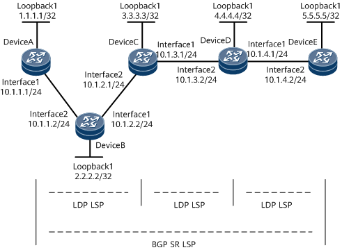
On the network shown in Figure 1, OSPF runs between DeviceA and DeviceB, between DeviceB and DeviceC, and between DeviceD and DeviceE. IS-IS runs between DeviceC and DeviceD. Basic MPLS capabilities and MPLS LDP are configured on DeviceA through DeviceE so that LDP LSPs are established between loopback interfaces of devices in each IGP area. Therefore, traffic between loopback interfaces of devices in each IGP area is encapsulated using MPLS. However, traffic cannot be transmitted across IGP areas because devices cannot ping each other across IGP areas. For example, DeviceA cannot ping DeviceE. To solve this problem, you need to configure an inner MPLS tunnel (BGP SR LSP) from 1.1.1.1 to 5.5.5.5 so that the traffic from 1.1.1.1 to 5.5.5.5 is forwarded through MPLS.
Procedure
- Configure an SRGB.
- Run the system-view command to enter the system view.
- Run the bgp { as-number-plain | as-number-dot } command to start BGP (with the local AS number specified) and enter the BGP view.
- Run the segment-routing global-block begin-value end-value command to configure a BGP SRGB.
- Run the commit command to commit the configuration.
- Configure a BGP peer relationship.
- Run the system-view command to enter the system view.
- Run the bgp as-number command to enter the BGP view.
- Run the peer ipv4-address as-number as-number command to specify the IP address of a peer and the number of the AS where the peer resides.
- Run the peer ipv4-address connect-interface interface-type interface-number [ ipv4-source-address ] command to specify a source interface and a source address to set up a TCP connection with the BGP peer.
- Run the commit command to commit the configuration.
- Configure DeviceC and DeviceD as RRs.
- Run the system-view command to enter the system view.
- Run the bgp as-number command to enter the BGP view.
- Run the ipv4-family unicast command to enter the IPv4 unicast address family view.
- Run the peer { ipv4-address | group-name } reflect-client command to configure an RR and specify its peer as a client.
Configure DeviceA and DeviceD as clients of DeviceC, and configure DeviceC and DeviceE as clients of DeviceD.
- Run the peer { ipv4-address | group-name } next-hop-local command to configure the device to set the next hop address to its own address when advertising routes to clients.
To enable DeviceC or DeviceD to change the next hop address of a route to the local address before advertising the route to clients, run the peer next-hop-local command on DeviceC or DeviceD for each related client.
- Run the commit command to commit the configuration.
- Enable the function to exchange labeled IPv4 routes.
- Run the system-view command to enter the system view.
- Run the bgp as-number command to enter the BGP view.
- Run the peer { ipv4-address | group-name } label-route-capability [ check-tunnel-reachable ] command to configure the device to exchange labeled IPv4 routes with a specified BGP peer.
- Run the commit command to commit the configuration.
- Configure the ingress for a BGP SR LSP.
- Run the system-view command to enter the system view.
- Run the route-policy route-policy-name permit node node command to create a route-policy.
- Run the apply mpls-label command to configure the device to allocate labels to IPv4 routes.
- Run the quit command to return to the system view.
- Run the bgp { as-number-plain | as-number-dot } command to enter the BGP view.
- Run the network ipv4-address [ mask | mask-length ] [ route-policy route-policy-name | route-filter route-filter-name ] [ non-relay-tunnel ] label-index label-index-value command to configure BGP to import a local route and specify an offset for the SRGB.
- Run the peer { ipv4-address | group-name } route-policy route-policy-name export command to apply the route-policy to the routes to be advertised to the specified BGP peer.
- Run the ipv4-family unicast command to enter the BGP-IPv4 unicast address family view.
- Run the peer peerIpv4Addr prefix-sid command to configure the device to exchange prefix SID information with the specified IPv4 peer.
- Run the commit command to commit the configuration.
- Configure a transit node for the BGP SR LSP.
- Run the system-view command to enter the system view.
- Run the route-policy route-policy-name permit node node command to create a route-policy.
- Run the if-match mpls-label command to match labeled IPv4 routes.
- Run the apply mpls-label command to configure the device to allocate labels to IPv4 routes.
- Run the quit command to return to the system view.
- Run the bgp { as-number-plain | as-number-dot } command to enter the BGP view.
- Run the peer { ipv4-address | group-name } route-policy route-policy-name export command to apply the route-policy to the routes to be advertised to the specified BGP peer.
- Run the ipv4-family unicast command to enter the BGP-IPv4 unicast address family view.
- Run the peer peerIpv4Addr prefix-sid command to configure the device to exchange prefix SID information with the specified IPv4 peer.
- Run the commit command to commit the configuration.
Verifying the Configuration
After configuring the function, verify the configuration.
- Run the display bgp routing-table ipv4-address [ mask | mask-length ] prefix-sid srgb command to check SRGB information of the BGP routes with a specified destination address.
- Run the display mpls lsp command to check BGP SR LSP information.