Example for Configuring VLAN-based BPDU Tunneling
In this example, provider edges (PEs) function as aggregation devices. An interface on a PE may receive bridge protocol data units (BPDUs) from different user networks, and the customer edges (CEs) add different virtual local area network (VLAN) IDs to the BPDUs to differentiate the user networks. To transparently transmit the BPDUs over the carrier network, you can deploy VLAN-based BPDU tunneling on the PEs and CEs.
Networking Requirements
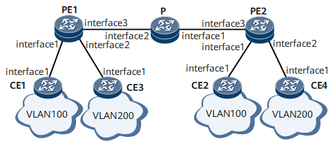
On the network shown in Figure 1, the CEs are connected to the PEs, and BPDUs exchanged between the CEs must be transparently transmitted by the PEs over the carrier network. The BPDUs received by each PE interface from CEs must carry VLAN tags for differentiating user networks. In this situation, you can configure VLAN-based BPDU tunneling to achieve the following:
The devices in VLAN 100 can complete the spanning tree calculation together.
The devices in VLAN 200 can complete the spanning tree calculation together.
This example describes the configuration on devices with the same role. In this scenario, the CEs and PEs are both customers, and the default well-known destination MAC address of BPDUs is 0180-C200-0000. The PEs cannot transparently transmit BPDUs sent by the CEs. In this case, you need to enable BPDU tunneling on the PE interfaces.
Configuration Roadmap
The configuration roadmap is as follows:
Enable the spanning tree calculation on the CEs and PEs.
Configure the CEs to add specified VLAN IDs to BPDUs before sending them to the PEs.
Disable the spanning tree calculation on the PE interfaces that are connected to the CEs, and configure the PEs to transparently transmit BPDUs.
Configure the PE interfaces that are connected to the carrier network to allow the passing of BPDUs with the VLAN IDs 100 and 200.
Configure the Layer 2 forwarding function on the P to transmit packets exchanged between the PEs over the carrier network.
Data Preparation
To complete the configuration, you need the following data:
VLAN IDs of BPDUs sent by the CEs to the PEs
IDs of the VLANs to which the interfaces on the PEs and CEs belong
Procedure
- Switch the interfaces on the PEs and CEs that transmit BPDUs to Layer 2 interfaces.

If an interface is a Layer 2 interface, skip this step.
Run the portswitch command to switch all the PE and CE interfaces in Figure 1 to Layer 2 interfaces. For configuration details, see "Configuration Files" in this section.
- Enable the spanning tree calculation on the CEs and PEs.
# Configure CE1.
[~CE1] stp enable
[*CE1] commit
# Configure CE2.
[~CE2] stp enable
[*CE2] commit
# Configure CE3.
[~CE3] stp enable
[*CE3] commit
# Configure CE4.
[~CE4] stp enable
[*CE4] commit
# Configure PE1.
[~PE1] stp enable
[*PE1] commit
# Configure PE2.
[~PE2] stp enable
[*PE2] commit
- Configure CE1 and CE2 to add the VLAN ID 100 to BPDUs before sending them to the PEs. Configure CE3 and CE4 to add the VLAN ID 200 to BPDUs before sending them to the PEs.
# Configure CE1.
[~CE1] vlan 100
[*CE1-vlan100] commit
[~CE1-vlan100] quit
[~CE1] interface gigabitethernet 0/1/1
[~CE1-GigabitEthernet0/1/1] port trunk allow-pass vlan 100
[*CE1-GigabitEthernet0/1/1] stp bpdu vlan 100
[*CE1-GigabitEthernet0/1/1] commit
# Configure CE2.
[~CE2] vlan 100
[*CE2-vlan100] commit
[~CE2-vlan100] quit
[~CE2] interface gigabitethernet 0/1/1
[~CE2-GigabitEthernet0/1/1] port trunk allow-pass vlan 100
[*CE2-GigabitEthernet0/1/1] stp bpdu vlan 100
[*CE2-GigabitEthernet0/1/1] commit
# Configure CE3.
[~CE3] vlan 200
[*CE3-vlan200] commit
[~CE3-vlan200] quit
[~CE3] interface gigabitethernet 0/1/1
[~CE3-GigabitEthernet0/1/1] port trunk allow-pass vlan 200
[*CE3-GigabitEthernet0/1/1] stp bpdu vlan 200
[*CE3-GigabitEthernet0/1/1] commit
# Configure CE4.
[~CE4] vlan 200
[*CE4-vlan200] commit
[~CE4-vlan200] quit
[~CE4] interface gigabitethernet 0/1/1
[~CE4-GigabitEthernet0/1/1] port trunk allow-pass vlan 200
[*CE4-GigabitEthernet0/1/1] stp bpdu vlan 200
[*CE4-GigabitEthernet0/1/1] commit
- Configure the PEs to replace the well-known destination MAC address of BPDUs received from the CEs.
# Configure PE1.
[~PE1] bpdu-tunnel stp group-mac 0100-5e00-0011
[*PE1] commit
# Configure PE2.
[~PE2] bpdu-tunnel stp group-mac 0100-5e00-0011
[*PE2] commit
- Configure the interfaces on the PEs to transparently transmit tagged BPDUs from the CEs to the P.
# Configure PE1.
[~PE1] vlan 100
[*PE1-vlan100] commit
[~PE1-vlan100] quit
[~PE1] vlan 200
[*PE1-vlan200] commit
[~PE1-vlan200] quit
[~PE1] interface gigabitethernet 0/1/3
[~PE1-GigabitEthernet0/1/3] port trunk allow-pass vlan 100 200
[*PE1-GigabitEthernet0/1/3] commit
[~PE1-GigabitEthernet0/1/3] quit
[~PE1] interface gigabitethernet 0/1/1
[~PE1-GigabitEthernet0/1/1] port trunk allow-pass vlan 100
[*PE1-GigabitEthernet0/1/1] bpdu-tunnel stp vlan 100
[*PE1-GigabitEthernet0/1/1] stp disable
[*PE1-GigabitEthernet0/1/1] commit
[~PE1-GigabitEthernet0/1/1] quit
[~PE1] interface gigabitethernet 0/1/2
[~PE1-GigabitEthernet0/1/2] port trunk allow-pass vlan 200
[*PE1-GigabitEthernet0/1/2] bpdu-tunnel stp vlan 200
[*PE1-GigabitEthernet0/1/2] stp disable
[*PE1-GigabitEthernet0/1/2] commit
[~PE1-GigabitEthernet0/1/2] quit
# Configure PE2.
[~PE2] vlan 100
[*PE2-vlan100] commit
[~PE2-vlan100] quit
[~PE2] vlan 200
[*PE2-vlan200] commit
[~PE2-vlan200] quit
[~PE2] interface gigabitethernet 0/1/3
[~PE2-GigabitEthernet0/1/3] port trunk allow-pass vlan 100 200
[*PE2-GigabitEthernet0/1/3] commit
[~PE2-GigabitEthernet0/1/3] quit
[~PE2] interface gigabitethernet 0/1/1
[~PE2-GigabitEthernet0/1/1] port trunk allow-pass vlan 100
[*PE2-GigabitEthernet0/1/1] bpdu-tunnel stp vlan 100
[*PE2-GigabitEthernet0/1/1] stp disable
[*PE2-GigabitEthernet0/1/1] commit
[~PE2-GigabitEthernet0/1/1] quit
[~PE2] interface gigabitethernet 0/1/2
[~PE2-GigabitEthernet0/1/2] port trunk allow-pass vlan 200
[*PE2-GigabitEthernet0/1/2] bpdu-tunnel stp vlan 200
[*PE2-GigabitEthernet0/1/2] stp disable
[*PE2-GigabitEthernet0/1/2] commit
[~PE2-GigabitEthernet0/1/2] quit
- Configure the Layer 2 forwarding function on the P and configure the P to allow the passing of packets with the VLAN IDs 100 and 200.
[~P] vlan 100
[*P-vlan100] commit
[~P-vlan100] quit
[~P] vlan 200
[*P-vlan200] commit
[~P-vlan200] quit
[~P] interface gigabitethernet 0/1/2
[~P-GigabitEthernet0/1/2] port trunk allow-pass vlan 100 200
[*P-GigabitEthernet0/1/2] commit
[~P-GigabitEthernet0/1/2] quit
[~P] interface gigabitethernet 0/1/1
[~P-GigabitEthernet0/1/1] port trunk allow-pass vlan 100 200
[*P-GigabitEthernet0/1/1] commit
[~P-GigabitEthernet0/1/1] quit
- Verify the configuration.
Run the display stp command on CE1 and CE2 to view the root bridge selected by the Multiple Spanning Tree Protocol (MSTP). The command output shows that CE1 and CE2 have completed the spanning tree calculation and that GE0/1/1 on CE1 is the Root interface and GE0/1/1 on CE2 is the Designated interface.
[~CE1] display stp
-------[CIST Global Info][Mode MSTP]-------
CIST Bridge         :32768.00e0-fc12-3457
Bridge Times        :Hello 2s MaxAge 20s FwDly 15s MaxHop 20
Active Times        :Hello 2s MaxAge 20s FwDly 15s MaxHop 19
CIST Root/ERPC      :32768.00e0-fc12-3459 / 199999
CIST RegRoot/IRPC   :32768.00e0-fc12-3457 / 0
CIST RootPortId     :128.82
BPDU-Protection     :disabled
TC or TCN received  :2
TC count per hello  :0
STP Converge Mode   :Normal
Time since last TC received :0 days 3h:53m:43s
Number of TC        :1
Last TC occurred    :GigabitEthernet0/1/1
----[Port17(GigabitEthernet0/1/1)][FORWARDING]----
 Port Protocol       :enabled
 Port Role           :CIST Root Port
 Port Priority       :128
 Port Cost(Dot1T )   :Config=auto / Active=199999
 Desg. Bridge/Port   :32768.00e0-fc12-3459 / 128.82
 Port Edged          :Config=disabled / Active=disabled
 Point-to-point      :Config=auto / Active=true
 Transit Limit       :3 packets/hello-time
 Protection Type     :None
 Port STP Mode       :MSTP
 Port Protocol Type  :Config=auto / Active=dot1s
 BPDU Encapsulation  :Config=stp / Active=stp
 PortTimes           :Hello 2s MaxAge 20s FwDly 15s RemHop 20
 TC or TCN send      :2
 TC or TCN received  :0
 BPDU Sent           :7
          TCN: 0, Config: 0, RST: 0, MST: 7
 BPDU Received       :105
          TCN: 0, Config: 0, RST: 0, MST: 105
[~CE2] display stp
-------[CIST Global Info][Mode MSTP]-------
CIST Bridge         :32768.00e0-fc12-3459
Bridge Times        :Hello 2s MaxAge 20s FwDly 15s MaxHop 20
Active Times        :Hello 2s MaxAge 20s FwDly 15s MaxHop 19
CIST Root/ERPC      :32768.00e0-fc12-3459 / 0
CIST RegRoot/IRPC   :32768.00e0-fc12-3459 / 0
CIST RootPortId     :0.0
BPDU-Protection     :disabled
TC or TCN received  :1
TC count per hello  :0
STP Converge Mode   :Normal
Time since last TC received :0 days 5h:29m:6s
Number of TC        :1
Last TC occurred    :GigabitEthernet0/1/1
----[Port17(GigabitEthernet0/1/1)][FORWARDING]----
 Port Protocol       :enabled
 Port Role           :CIST Designated Port
 Port Priority       :128
 Port Cost(Dot1T )   :Config=auto / Active=199999
 Desg. Bridge/Port   :32768.00e0-fc12-3459 / 128.82
 Port Edged          :Config=disabled / Active=disabled
 Point-to-point      :Config=auto / Active=true
 Transit Limit       :3 packets/hello-time
 Protection Type     :None
 Port STP Mode       :MSTP
 Port Protocol Type  :Config=auto / Active=dot1s
 BPDU Encapsulation  :Config=stp / Active=stp
 PortTimes           :Hello 2s MaxAge 20s FwDly 15s RemHop 20
 TC or TCN send      :2
 TC or TCN received  :0
 BPDU Sent           :237
          TCN: 0, Config: 0, RST: 0, MST: 237
 BPDU Received       :120
          TCN: 0, Config: 0, RST: 0, MST: 120
Run the display stp command on CE3 and CE4 to view the root bridge selected by MSTP. The command output shows that CE3 and CE4 have completed the spanning tree calculation. GE0/1/1 on CE3 is the Root interface and GE0/1/1 on CE4 is the Designated interface.
[~CE3] display stp
-------[CIST Global Info][Mode MSTP]-------
CIST Bridge         :32768.00e0-fc12-3458
Bridge Times        :Hello 2s MaxAge 20s FwDly 15s MaxHop 20
Active Times        :Hello 2s MaxAge 20s FwDly 15s MaxHop 19
CIST Root/ERPC      :32768.00e0-fc12-3456 / 199999
CIST RegRoot/IRPC   :32768.00e0-fc12-3458 / 0
CIST RootPortId     :128.82
BPDU-Protection     :disabled
TC or TCN received  :4
TC count per hello  :0
STP Converge Mode   :Normal
Time since last TC received :0 days 3h:57m:0s
Number of TC        :1
Last TC occurred    :GigabitEthernet0/1/1
----[Port17(GigabitEthernet0/1/1)][FORWARDING]----
 Port Protocol       :enabled
 Port Role           :CIST Root Port
 Port Priority       :128
 Port Cost(Dot1T )   :Config=auto / Active=199999
 Desg. Bridge/Port   :32768.00e0-fc12-3456 / 128.82
 Port Edged          :Config=disabled / Active=disabled
 Point-to-point      :Config=auto / Active=true
 Transit Limit       :3 packets/hello time
 Protection Type     :None
 Port STP Mode       :MSTP
 Port Protocol Type  :Config=auto / Active=dot1s
 BPDU Encapsulation  :Config=stp / Active=stp
 PortTimes           :Hello 2s MaxAge 20s FwDly 15s RemHop 20
 TC or TCN send      :2
 TC or TCN received  :0
 BPDU Sent           :17
          TCN: 0, Config: 0, RST: 0, MST: 17
 BPDU Received       :105
          TCN: 0, Config: 0, RST: 0, MST: 105
[~CE4] display stp
-------[CIST Global Info][Mode MSTP]-------
CIST Bridge         :32768.00e0-fc12-3456
Bridge Times        :Hello 2s MaxAge 20s FwDly 15s MaxHop 20
Active Times        :Hello 2s MaxAge 20s FwDly 15s MaxHop 19
CIST Root/ERPC      :32768.00e0-fc12-3456 / 0
CIST RegRoot/IRPC   :32768.00e0-fc12-3456 / 0
CIST RootPortId     :0.0
BPDU-Protection     :disabled
TC or TCN received  :2
TC count per hello  :0
STP Converge Mode   :Normal
Time since last TC received :0 days 5h:33m:17s
Number of TC        :1
Last TC occurred    :GigabitEthernet0/1/1
----[Port17(GigabitEthernet0/1/1)][FORWARDING]----
 Port Protocol       :enabled
 Port Role           :CIST Designated Port
 Port Priority       :128
 Port Cost(Dot1T )   :Config=auto / Active=199999
 Desg. Bridge/Port   :32768.00e0-fc12-3456 / 128.82
 Port Edged          :Config=disabled / Active=disabled
 Point-to-point      :Config=auto / Active=true
 Transit Limit       :3 packets/hello time
 Protection Type     :None
 Port STP Mode       :MSTP
 Port Protocol Type  :Config=auto / Active=dot1s
 BPDU Encapsulation  :Config=stp / Active=stp
 PortTimes           :Hello 2s MaxAge 20s FwDly 15s RemHop 20
 TC or TCN send      :2
 TC or TCN received  :0
 BPDU Sent           :11
          TCN: 0, Config: 0, RST: 0, MST: 11
 BPDU Received       :105
          TCN: 0, Config: 0, RST: 0, MST: 105
Configuration Files
CE1 configuration file
#
 sysname CE1
#
 vlan batch 100
#
 stp enable
#
interface GigabitEthernet0/1/1
 undo shutdown
 portswitch
 port trunk allow-pass vlan 100
 stp bpdu vlan 100
#
return
CE2 configuration file
#
 sysname CE2
#
 vlan batch 100
#
 stp enable
#
interface GigabitEthernet0/1/1
 undo shutdown
 portswitch
 port trunk allow-pass vlan 100
 stp bpdu vlan 100
#
return
CE3 configuration file
#
 sysname CE3
#
 vlan batch 200
#
 stp enable
#
interface GigabitEthernet0/1/1
 undo shutdown
 portswitch
 port trunk allow-pass vlan 200
 stp bpdu vlan 200
#
return
CE4 configuration file
#
 sysname CE4
#
 vlan batch 200
#
 stp enable
#
interface GigabitEthernet0/1/1
 undo shutdown
 portswitch
 port trunk allow-pass vlan 200
 stp bpdu vlan 200
#
Return
PE1 configuration file
#
 sysname PE1
#
 vlan batch 100 200
#
 bpdu-tunnel stp group-mac 0100-5e00-0011
#
 stp enable
#
interface GigabitEthernet0/1/1
 undo shutdown
 portswitch
 port trunk allow-pass vlan 100
 bpdu-tunnel stp vlan 100
 stp disable
#
interface GigabitEthernet0/1/2
 undo shutdown
 portswitch
 port trunk allow-pass vlan 200
 bpdu-tunnel stp vlan 200
 stp disable
#
interface GigabitEthernet0/1/3
 undo shutdown
 portswitch
 port trunk allow-pass vlan 100 200
#
return
P configuration file
#
 sysname P
#
 vlan batch 100 200
#
interface GigabitEthernet0/1/1
 undo shutdown
 portswitch
 port trunk allow-pass vlan 100 200
#
interface GigabitEthernet0/1/2
 undo shutdown
 portswitch
 port trunk allow-pass vlan 100 200
#
return
PE2 configuration file
#
 sysname PE2
#
 vlan batch 100 200
#
 bpdu-tunnel stp group-mac 0100-5e00-0011
#
 stp enable
#
interface GigabitEthernet0/1/1
 undo shutdown
 portswitch
 port trunk allow-pass vlan 100
 bpdu-tunnel stp vlan 100
 stp disable
#
interface GigabitEthernet0/1/2
 undo shutdown
 portswitch
 port trunk allow-pass vlan 200
 bpdu-tunnel stp vlan 200
 stp disable
#
interface GigabitEthernet0/1/3
 undo shutdown
 portswitch
 port trunk allow-pass vlan 100 200
#
return