Overview of Y.1731
Y.1731 is an operation, administration and maintenance (OAM) protocol defined by the ITU-T. It is used to implement end-to-end connectivity detection, loopback detection, and link trace Metro Ethernets (MEs). It also provides the test diagnosis and performance monitoring functions such as frame loss measurement, frame delay measurement, frame jitter measurement, and throughput measurement.
Background
Originally, Ethernet was mainly used in local area networks (LANs), and had a poor OAM capability. In addition, Ethernet supports only the network element-level management system that cannot meet network management requirements of most network operators. After Ethernet is widely used in MANs, the requirement on OAM becomes increasingly high.
Hierarchical Ethernet OAM needs to be provided based on the network architecture, as shown in Figure 1.
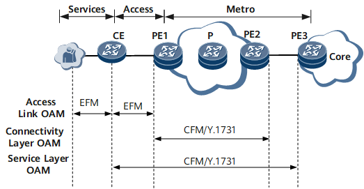
802.3ah, also known as Ethernet in the First Mile (EFM), is used to monitor first-mile link connectivity. It is a type of link-level OAM technology. EFM provides link connectivity detection, link fault monitoring, remote fault notification, and remote loopback for two directly connected devices.
IEEE 802.1ag, also known as Connectivity Fault Management (CFM), defines OAM functions, such as continuity check (CC), link trace (LT) and loopback (LB), for Ethernet networks. CFM is network-level OAM and is applicable to large-scale end-to-end networking.
Y.1731 is an OAM protocol defined by the ITU-T. It covers the contents defined by IEEE 802.1ag and other OAM functions, including the alarm indication signal (AIS), remote defect indication (RDI), locked signal (LCK), Test Signal, maintenance communication channel (MCC), experimental OAM (EXP), and vendor specific OAM (VSP) for fault management and frame loss measurement (LM) and delay measurement (DM) for performance monitoring.
As shown in Figure 1, Y.1731 is used to implement fast fault detection and performance monitoring for end-to-end services. When a user considers that the quality of purchased Ethernet tunnel services deteriorates or when an operator needs to conduct regular Service level agreement (SLA) monitoring.
Basic Concepts and Principles
Single-ended frame loss measurement
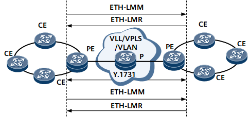
Frame loss measurement is performed by sending frames with ETH-LM information to a remote maintenance association end point (MEP) and receiving frames with ETH-LM information from the remote MEP. As shown in Figure 2, the process of single-ended frame loss measurement is as follows:The local MEP sends an ETH-LMM (a frame containing ETH-LM request information) to the remote MEP. The ETH-LMM carries a transmit counter indicating the time at which the message is sent by the local end.
After receiving the ETH-LMM, the remote MEP replies with an ETH-LMR (a frame containing ETH-LM response information).
After receiving the ETH-LMR, the local MEP obtains corresponding measurement information based on message contents and calculates the frame loss ratio.
Dual-ended frame loss measurement
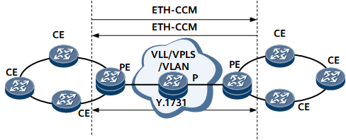
Frame loss measurement is performed by sending frames with ETH-LM information to a remote MEP and receiving frames with ETH-LM information from the remote MEP. As shown in Figure 3, the process of dual-ended frame loss measurement is as follows:Each MEP sends a frame containing ETH-LM request information to remote MEPs. Here, the frame containing ETH-LM request information is called a continuity check message (CCM).
Each MEP processes the received CCMs and measures the number of frames lost on both the local and remote ends.
Each MEP obtains corresponding measurement information based on contents in the CCMs and calculates frame loss ratios.
One-way frame delay measurement
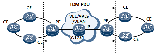
One-way frame delay measurement is performed between end-to-end MEPs by sending and receiving 1DM frames. As shown in Figure 4, the process of one-way frame delay measurement is as follows:A MEP periodically sends 1DM frames carrying TxTimeStampf.
After receiving a 1DM frame, the remote MEP compares the TxTimeStampf with the RxTimef that is the time at the reception of the frame, and then calculates the one-way frame delay by using the following formula:
Frame delay = RxTimef - TxTimeStampf
Two-way frame delay measurement
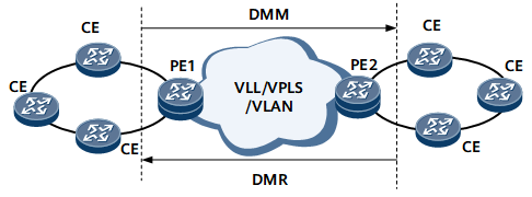
Two-way frame delay measurement is performed between end-to-end MEPs by sending and receiving delay measurement messages (DMMs) and delay measurement replies (DMRs). As shown in Figure 5, the process of two-way frame delay measurement is as follows:A MEP periodically sends DMMs carrying TxTimeStampf.
After receiving a DMM, the remote MEP adds the RxTimeStampf value (the time of receiving the DMM) to the DMM, generates a DMR with the TxTimeStampb value (the time of sending the DMR), and sends the frame to the requesting MEP. Every field in the DMM is copied to the DMR, except that the source and destination MAC addresses are swapped and the message type is changed from DMM to DMR.
Upon receiving the DMR frame, the requesting MEP calculates the two-way frame delay based on the following formula: The formula is as follows:
Frame delay = (RxTimeb - TxTimeStampf) - (TxTimeStampb - RxTimeStampf)
Ethernet test signal test
The ETH-Test functions are provided to test unidirectional on-demand services or diagnose service interruptions of on-demand services. ETH-Test functions include throughput tests, frame loss ratio tests, and bit error tests.
Maximum bandwidth: Test packets are sent at a specified speed. After a specified period of time, a node collects the number of sent packets and the number of received packets. If the number of sent packets is greater than the number of received packets, packets were discarded. Then test packets are sent at a smaller speed. After a specified period of time, a node collects the number of sent packets and the number of received packets. This process repeats until no packets are discarded. The transmission rate at which test packets are transmitted without being discarded is the throughput for the link.
Code errors: Test packets carry the CRC code in the Test TLV field. One of the following codes can be specified for test packets:
- Null signal without CRC-32: Packets carrying all 0s
- Null signal with CRC-32
- PRBS 2-31-1 without CRC-32: Pseudo Random Binary Sequence (PRBS) is used to simulate a white noise scenario
- PRBS 2-31-1 with CRC-32
A node sends ETH-test packets carrying calculated CRC code to its peer node. Upon receipt, the peer node re-calculates a CRC code. If the received CRC code is the same as the calculated CRC code, no code error occurs. If the two codes are different, a code error occurs.
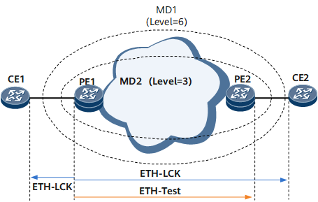
Ethernet test signal test (ETH-LCK)
The ETH-LCK function performs administrative locks (mainly involving alarm suppression) on outer MEPs within higher-level MDs. This function enables outer MEPs to distinguish inner MD fault-triggered alarm suppression (AIS) and inner MD administrative lock-triggered alarm suppression (LCK).
In Figure 6, MD2 with level 3 is configured on PE1 and PE2. MD1 with level 6 is configured on CE1 and CE2. After MEP1 on PE1 initiates an offline ETH-test instance to MEP2 on PE2, MEP1 also sends an ETH-LCK packet to MEP11 on CE1 and MEP22 on CE2 to suppress alarms on MEP11 and MEP22. After the offline ETH-Test instance ends on MEP1, MEP1 stops sending ETH-LCK packets. After MEP11 and MEP22 do not receive ETH-LCK packets within a period of time 3.5 times as long as the interval at which ETH-LCK packets are sent, MEP11 and MEP22 stop alarm suppression.
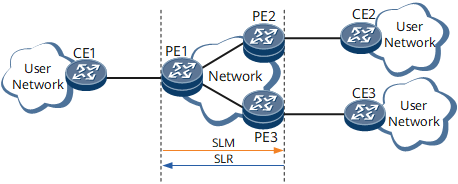
Single-ended synthetic loss measurement (SLM)
SLM measures frame loss using synthetic frames instead of data traffic. When implementing SLM, the local MEP exchanges frames containing ETH-SLM information with one or more RMEPs.
Figure 7 demonstrates the process of single-ended SLM:
- The local MEP sends frames with the ETH-SLM request information to the RMEPs.
- After receiving the frames with the ETH-SLM request information, the RMEPs send frames with the ETH-SLM reply information to the local MEP.
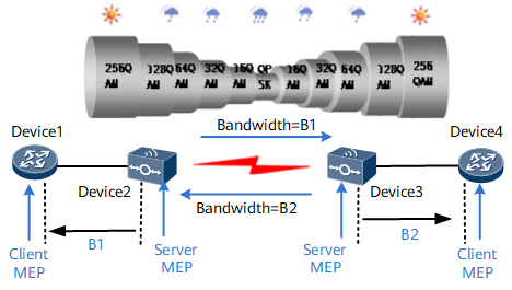
ETH-BN
Ethernet bandwidth notification (ETH-BN) enables server-layer MEPs to notify client-layer MEPs of the server layer's connection bandwidth when routing devices connect to microwave devices. The server-layer devices are microwave devices, which dynamically adjust the bandwidth according to the prevailing atmospheric conditions. The client-layer devices are routing devices. Routing devices can only function as ETH-BN packets' receive ends and must work with microwave devices to implement this function.
As shown in Figure 8, server-layer MEPs are configured on the server-layer devices, and the ETH-BN sending function is enabled. The levels of client-layer MEPs must be specified for the server-layer MEPs when the ETH-BN sending function is enabled. Client-layer MEPs are configured on the client-layer devices, and the ETH-BN receiving function is enabled. The levels of the client-layer MEPs are the same as those specified for the server-layer MEPs.If the ETH-BN function has been enabled on the server-layer devices Device2 and Device3 and the bandwidth of the server-layer devices' microwave links decreases, the server-layer devices send ETH-BN packets to the client-layer devices (Device1 and Device4). After receiving the ETH-BN packets, the client-layer MEPs can use bandwidth information in the packets to adjust service policies, for example, to reduce the rate of traffic sent to the degraded links.
When the server-layer devices' microwave links work properly, whether to send ETH-BN packets is determined by the configuration of the server-layer devices. When the server-layer microwave devices stop sending ETH-BN packets, the client-layer devices do not receive any ETH-BN packets. The ETH-BN data on the client-layer devices is aged after 3.5 times the interval at which ETH-BN packets are sent.

When planning ETH-BN, you must check that the service burst traffic is consistent with a device's buffer capability.