Example for Configuring Dual-ended Frame Loss Measurement in VLL Networking
This section provides an example showing how to configure dual-ended frame loss measurement in VLL networking.
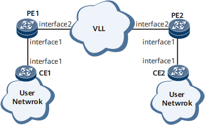
Networking Requirements
With the increasing popularization and wide application of the Internet, various value-added services such as IPTV, video conferencing, and VoIP services are widely deployed. Link connectivity and network performance determine the Quality of Services (QoS) on bearer networks. Therefore, performance monitoring is especially important for service transmission channels.
As shown in Figure 1, CFM is configured between each CE and PE and between PEs. To provide high-quality audio services, providers hope to monitor the frame loss over mobile bearer links in real time, while monitoring link connectivity. Monitoring the frame loss over mobile bearer links allows the providers to respond quickly to video service quality deterioration.

Configuration Roadmap
Configure on-demand dual-ended frame loss measurement for the PW between the PEs to periodically collect frame loss statistics.
Data Preparation
To complete the configuration, you need the following data:
Configure the ID of an L2VC of a VLL between PE1 and PE2.
Configure the names of the MD and MA between PE1 and PE2 and between CE1 and PE1.
Configure the interval at which LM messages are sent.
Procedure
- Configure dual-ended frame loss measurement for the PW based on ACs on PEs.
Configure a VLL connection.
Configure a VLL connection between PE1 and PE2. The configuration details are not provided here. For details, see the chapter "VLL Configuration" in the HUAWEI NetEngine 8000 F Series Router Configuration Guide - VPN or configuration files in this configuration example.
After completing the configuration, run the display mpls l2vc command on each PE to view information about the VC and AC.
[~PE1] display mpls l2vc
 total LDP VC : 1     1 up       0 down

 *client interface       : Gigabitethernet0/1/1.1
  Administrator PW       : no
  session state          : up
  AC status              : up
  VC state               : up
  Label state            : 0
  Token state            : 0
  VC ID                  : 1001
  VC type                : GigabitEthernet
  destination            : 2.2.2.2
  local VC label         : 16             remote VC label      : 16
  control word           : disable
  remote control word    : disable
  forwarding entry       : exist
  local group ID         : 0
  remote group ID        : 0   local AC OAM State     : up   local PSN OAM State    : up   local forwarding state : forwarding   local status code      : 0x0   remote AC OAM state    : up   remote PSN OAM state   : up   remote forwarding state: forwarding   remote status code     : 0x0   ignore standby state   : no   BFD for PW             : unavailable   VCCV State             : up
  manual fault           : not set
  active state           : active
  OAM Protocol           : --
  OAM Status             : --
  OAM Fault Type         : --
  PW APS ID              : --
  PW APS Status          : --
  TTL Value              : 1
  link state             : up
  local VC MTU           : 1500           remote VC MTU        : 1500
  local VCCV             : alert ttl lsp-ping bfd   remote VCCV            : alert ttl lsp-ping bfd
  tunnel policy name     : --
  traffic behavior name  : --
  PW template name       : --
  primary or secondary   : primary
  load balance type      : flow
  Access-port            : false
  Switchover Flag        : false   VC tunnel info         : 1 tunnels     NO.0  TNL type       : ldp   , TNL ID : 0x0000000001004c4e42
  create time            : 4 days, 15 hours, 59 minutes, 12 seconds
  up time                : 0 days, 15 hours, 23 minutes, 17 seconds
  last change time       : 0 days, 15 hours, 23 minutes, 17 seconds
  VC last up time        : 2012/07/24 09:37:33
  VC total up time       : 4 days, 15 hours, 57 minutes, 50 seconds
  CKey                   : 1
  NKey                   : 436207716
  PW redundancy mode     : frr
  AdminPw interface      : --
  AdminPw link state     : --
  Forward state          : send inactive, receive inactive
  Diffserv Mode          : uniform
  Service Class          : --
  Color                  : --
  DomainId               : --
  Domain Name            : --
Configure basic Ethernet CFM functions and specify the maintenance association end point (MEP) type as inward.
Configure basic Ethernet CFM functions on each PE. Specify the Ethernet CFM protocol in the version of IEEE Standard 802.1ag-2007. Create an MD named md1 and an MA named ma1, and bind the MA to the VLL.
# Configure PE1.
<HUAWEI> system-view
[~HUAWEI] sysname PE1
[*HUAWEI] commit
[~PE1] cfm enable
[*PE1] commit
[*PE1] cfm md md1
[*PE1-md-md1] ma ma1
[*PE1-md-md1-ma-ma1] map mpls l2vc 2 tagged
[*PE1-md-md1-ma-ma1] mep mep-id 1 interface gigabitethernet0/1/1.1 inward
[*PE1-md-md1-ma-ma1] remote-mep mep-id 2
[*PE1-md-md1-ma-ma1] mep ccm-send mep-id 1 enable
[*PE1-md-md1-ma-ma1] remote-mep ccm-receive mep-id 2 enable
[*PE1-md-md1-ma-ma1] test-id 1 mep 1 remote-mep 2
[*PE1-md-md1-ma-ma1] commit
# Configure PE2.
<HUAWEI> system-view
[~HUAWEI] sysname PE2
[*HUAWEI] commit
[~PE2] cfm enable
[*PE2] commit
[*PE2] cfm md md1
[*PE2-md-md1] ma ma1
[*PE2-md-md1-ma-ma1] map mpls l2vc 2 tagged
[*PE2-md-md1-ma-ma1] mep mep-id 2 interface gigabitethernet0/1/1.1 inward
[*PE2-md-md1-ma-ma1] remote-mep mep-id 1
[*PE2-md-md1-ma-ma1] mep ccm-send mep-id 2 enable
[*PE2-md-md1-ma-ma1] remote-mep ccm-receive mep-id 1 enable
[*PE2-md-md1-ma-ma1] test-id 1 mep 2 remote-mep 1
[*PE2-md-md1-ma-ma1] commit
Enable dual-ended frame loss measurement on the VLL network.
# Configure PE1.
[~PE1-md-md1-ma-ma1] loss-measure dual-ended continual test-id 1
[*PE1-md-md1-ma-ma1] quit
[*PE1-md-md1] quit
[*PE1] commit
# Configure PE2.
[~PE2-md-md1-ma-ma1] loss-measure dual-ended continual test-id 1
[*PE2-md-md1-ma-ma1] quit
[*PE2-md-md1] quit
[*PE2] commit
Verify the configuration.
Run the display y1731 statistic-type command on PE1 to view dual-ended frame loss statistics.
[~PE1] display y1731 statistic-type dual-loss
Latest dual-ended loss statistics of test-id 1:
--------------------------------------------------------------------------------
Index    Local-loss    Local-loss ratio    Remote-loss    Remote-loss ratio
--------------------------------------------------------------------------------
    1             0             0.0000%              0              0.0000%
    2             0             0.0000%              0              0.0000%
    3             0             0.0000%              0              0.0000%
    4             0             0.0000%              0              0.0000%
    5             0             0.0000%              0              0.0000%
    6             0             0.0000%              0              0.0000%
    7             0             0.0000%              0              0.0000%
    8             0             0.0000%              0              0.0000%
    9             0             0.0000%              0              0.0000%
--------------------------------------------------------------------------------
Average Local-loss  :          0    Average Local-loss Ratio  :   0.0000%
Maximum Local-loss  :          0    Maximum Local-loss Ratio  :   0.0000%
Minimum Local-loss  :          0    Minimum Local-loss Ratio  :   0.0000%
Average Remote-loss :          0    Average Remote-loss Ratio :   0.0000%
Maximum Remote-loss :          0    Maximum Remote-loss Ratio :   0.0000%
Minimum Remote-loss :          0    Minimum Remote-loss Ratio :   0.0000%
Configuration Files
PE1 configuration file
#
 sysname PE1
#
 cfm version standard
 cfm enable
#
 mpls lsr-id 1.1.1.1
 mpls
#
 mpls l2vpn
#
mpls ldp
#
interface GigabitEthernet0/1/1.1
 vlan-type dot1q 2
 mpls l2vc 2.2.2.2 2
#
interface GigabitEthernet0/1/2
 undo shutdown
 ip address 10.1.1.1 255.255.255.0
 mpls
 mpls ldp
#
interface LoopBack0
 ip address 1.1.1.1 255.255.255.0
#
ospf 1
 area 0.0.0.0
  network 1.1.1.1 0.0.0.0
  network 10.1.1.0 0.0.0.255
#
 cfm md md1
  ma ma1
   map mpls l2vc 2 tagged
   mep mep-id 1 interface GigabitEthernet0/1/1.1 inward
   mep ccm-send mep-id 1 enable
   remote-mep mep-id 2
   remote-mep ccm-receive mep-id 2 enable
   test-id 1 mep 1 remote-mep 2
   loss-measure dual-ended continual test-id 1
#
return
PE2 configuration file
#
 sysname PE2
#
 cfm version standard
 cfm enable
#
 mpls lsr-id 2.2.2.2
 mpls
#
 mpls l2vpn
#
mpls ldp
#
interface GigabitEthernet0/1/1.1
 vlan-type dot1q 2
 mpls l2vc 1.1.1.1 2
#
interface GigabitEthernet0/1/2
 undo shutdown
 ip address 10.1.1.2 255.255.255.0
 mpls
 mpls ldp
#
interface LoopBack0
 ip address 2.2.2.2 255.255.255.0
#
ospf 1
 area 0.0.0.0
  network 2.2.2.2 0.0.0.0
  network 10.1.1.0 0.0.0.255
#
 cfm md md1
  ma ma1
   map mpls l2vc 2 tagged
   mep mep-id 2 interface GigabitEthernet0/1/1.1 inward
   mep ccm-send mep-id 2 enable
   remote-mep mep-id 1
   remote-mep ccm-receive mep-id 1 enable
   test-id 1 mep 2 remote-mep 1
   loss-measure dual-ended continual test-id 1
#
return