Example for Configuring eMDI Detection on an Intra-AS NG MVPN with an mLDP P2MP LSP
This section provides an example for configuring eMDI detection on an intra-AS NG MVPN to carry multicast traffic over an mLDP P2MP LSP.
Networking Requirements
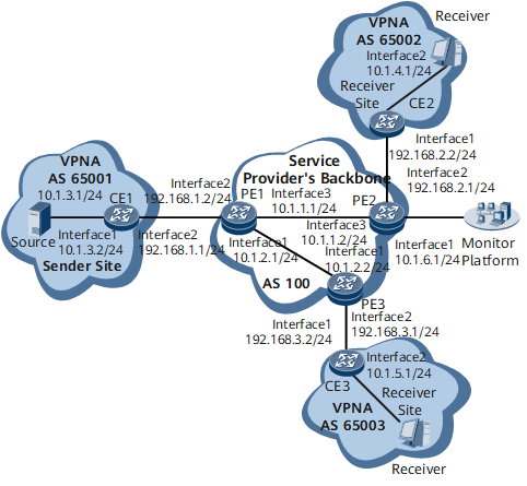
On the network shown in Figure 1, a BGP MPLS/IP VPN over an MPLS LDP LSP is deployed to carry unicast services, and an NG MVPN over an mLDP P2MP LSP is deployed to carry multicast services. In addition, eMDI is deployed on the network to monitor multicast service quality. Network maintenance personnel can check real-time detection results reported through telemetry on the monitor platform, quickly demarcating and locating faults.

Configuration Roadmap
The configuration roadmap is as follows:
Configure a BGP MPLS/IP VPN.
Enable mLDP globally.
Configure an NG MVPN.
Configure eMDI detection.
- Configure eMDI to monitor a channel group.
- Configure eMDI to monitor a board group.
- Bind a channel group to a board group.
Configure telemetry.
Data Preparation
To complete the configuration, you need the following data:
Public network OSPF process ID: 1; area ID: 0 OSPF multi-instance process ID: 2; area ID: 0
- VPN instance name on PE1, PE2, and PE3: VPNA
Table 1 Data needed for each device Device
IP Address of Loopback 1
MPLS LSR ID
MVPN ID
RD
VPN Target
AS Number
CE1 configuration file
1.1.1.1
-
-
-
-
AS65001
PE1
2.2.2.2
2.2.2.2
2.2.2.2
200:1
3:3 4:4
AS100
PE2
3.3.3.3
3.3.3.3
3.3.3.3
300:1
3:3
AS100
PE3
4.4.4.4
4.4.4.4
4.4.4.4
400:1
4:4
AS100
CE2
5.5.5.5
-
-
-
-
AS65002
CE3
6.6.6.6
-
-
-
-
AS65003
- Channel group names and board group names
Procedure
- Configure a BGP MPLS/IP VPN.
- Enable mLDP globally.
# Configure PE1.
[~PE1] mpls ldp
[*PE1-mpls-ldp] mldp p2mp
[*PE1-mpls-ldp] commit
[~PE1-mpls-ldp] quit
# Configure PE2.
[~PE2] mpls ldp
[*PE2-mpls-ldp] mldp p2mp
[*PE2-mpls-ldp] commit
[~PE2-mpls-ldp] quit
# Configure PE3.
[~PE3] mpls ldp
[*PE3-mpls-ldp] mldp p2mp
[*PE3-mpls-ldp] commit
[~PE3-mpls-ldp] quit
- Configure an NG MVPN.
- Establish a BGP MVPN peer relationship between the PEs.
# Configure PE1.
[~PE1] bgp 100
[*PE1-bgp] ipv4-family mvpn
[*PE1-bgp-af-mvpn] peer 3.3.3.3 enable
[*PE1-bgp-af-mvpn] peer 4.4.4.4 enable
[*PE1-bgp-af-mvpn] commit
[~PE1-bgp-af-mvpn] quit
[~PE1-bgp] quit
# Configure PE2.
[~PE2] bgp 100
[*PE2-bgp] ipv4-family mvpn
[*PE2-bgp-af-mvpn] peer 2.2.2.2 enable
[*PE2-bgp-af-mvpn] commit
[~PE2-bgp-af-mvpn] quit
[~PE2-bgp] quit
# Configure PE3.
[~PE3] bgp 100
[*PE3-bgp] ipv4-family mvpn
[*PE3-bgp-af-mvpn] peer 2.2.2.2 enable
[*PE3-bgp-af-mvpn] commit
[~PE3-bgp-af-mvpn] quit
[~PE3-bgp] quit
After the configuration is complete, run the display bgp mvpn all peer command on the PEs. The command output shows that PE1 has established a BGP MVPN peer relationship with PE2 and PE3. The following example uses the command output on PE1.
[~PE1] display bgp mvpn all peer
 BGP local router ID : 10.1.2.1
 Local AS number : 100
 Total number of peers : 2                 Peers in established state : 2

  Peer            V          AS  MsgRcvd  MsgSent  OutQ  Up/Down       State  PrefRcv
  3.3.3.3         4         100       43       42     0 00:29:28 Established        2
  4.4.4.4         4         100       32       35     0 00:21:59 Established        1
- Configure each PE to use mLDP to establish an S-PMSI tunnel.
# Configure PE1.
[~PE1] multicast mvpn 2.2.2.2
[*PE1] ip vpn-instance VPNA
[*PE1-vpn-instance-VPNA] ipv4-family
[*PE1-vpn-instance-VPNA-af-ipv4] multicast routing-enable
[*PE1-vpn-instance-VPNA-af-ipv4] mvpn
[*PE1-vpn-instance-VPNA-af-ipv4-mvpn] sender-enable
[*PE1-vpn-instance-VPNA-af-ipv4-mvpn] c-multicast signaling bgp
[*PE1-vpn-instance-VPNA-af-ipv4-mvpn] rpt-spt mode
[*PE1-vpn-instance-VPNA-af-ipv4-mvpn] ipmsi-tunnel
[*PE1-vpn-instance-VPNA-af-ipv4-mvpn-ipmsi] mldp
[*PE1-vpn-instance-VPNA-af-ipv4-mvpn-ipmsi] quit
[*PE1-vpn-instance-VPNA-af-ipv4-mvpn] spmsi-tunnel
[*PE1-vpn-instance-VPNA-af-ipv4-mvpn-spmsi] group 224.0.0.0 255.255.255.0 mldp limit 1
[*PE1-vpn-instance-VPNA-af-ipv4-mvpn-spmsi] quit
[*PE1-vpn-instance-VPNA-af-ipv4-mvpn] quit
[*PE1-vpn-instance-VPNA-af-ipv4] quit
[*PE1-vpn-instance-VPNA] quit
[*PE1] commit
# Configure PE2.
[~PE2] multicast mvpn 3.3.3.3
[*PE2] ip vpn-instance VPNA
[*PE2-vpn-instance-VPNA] ipv4-family
[*PE2-vpn-instance-VPNA-af-ipv4] multicast routing-enable
[*PE2-vpn-instance-VPNA-af-ipv4] mvpn
[*PE2-vpn-instance-VPNA-af-ipv4-mvpn] c-multicast signaling bgp
[*PE2-vpn-instance-VPNA-af-ipv4-mvpn] rpt-spt mode
[*PE2-vpn-instance-VPNA-af-ipv4-mvpn] quit
[*PE2-vpn-instance-VPNA-af-ipv4] quit
[*PE2-vpn-instance-VPNA] quit
[*PE2] commit
# Configure PE3.
[~PE3] multicast mvpn 4.4.4.4
[*PE3] ip vpn-instance VPNA
[*PE3-vpn-instance-VPNA] ipv4-family
[*PE3-vpn-instance-VPNA-af-ipv4] multicast routing-enable
[*PE3-vpn-instance-VPNA-af-ipv4] mvpn
[*PE3-vpn-instance-VPNA-af-ipv4-mvpn] c-multicast signaling bgp
[*PE3-vpn-instance-VPNA-af-ipv4-mvpn] rpt-spt mode
[*PE3-vpn-instance-VPNA-af-ipv4-mvpn] quit
[*PE3-vpn-instance-VPNA-af-ipv4] quit
[*PE3-vpn-instance-VPNA] quit
[*PE3] commit
After completing the configuration, run the display mvpn vpn-instance ipmsi command on the PEs to check I-PMSI tunnel information. The following example uses the command output on PE1.
[~PE1] display mvpn vpn-instance VPNA ipmsi
MVPN local i-PMSI information for VPN-Instance: VPNA
Tunnel type: mLDP P2MP LSP
Tunnel state: Up
Root-ip: 2.2.2.2
Opaque value: 0x01000400008021
Root: 2.2.2.2 (local)
Leaf:
  1: 3.3.3.3
  2: 4.4.4.4
The command output shows that an mLDP P2MP LSP has been established, with PE1 as the root node and PE2 and PE3 as leaf nodes.
- Configure PIM.
# Configure PE1.
[*PE1] interface gigabitethernet0/1/1
[*PE1-GigabitEthernet0/1/1] pim sm
[*PE1-GigabitEthernet0/1/1] quit
[*PE1] commit
# Configure CE1.
[~CE1] multicast routing-enable
[*CE1] interface gigabitethernet0/1/0
[*CE1-GigabitEthernet0/1/0] pim sm
[*CE1-GigabitEthernet0/1/0] quit
[*CE1] interface gigabitethernet0/1/1
[*CE1-GigabitEthernet0/1/1] pim sm
[*CE1-GigabitEthernet0/1/1] quit
[*CE1] commit
# Configure PE2.
[*PE2] interface gigabitethernet0/1/1
[*PE2-GigabitEthernet0/1/1] pim sm
[*PE2-GigabitEthernet0/1/1] quit
[*PE2] commit
# Configure CE2.
[~CE2] multicast routing-enable
[*CE2] interface gigabitethernet0/1/0
[*CE2-GigabitEthernet0/1/0] pim sm
[*CE2-GigabitEthernet0/1/0] quit
[*CE2] interface gigabitethernet0/1/1
[*CE2-GigabitEthernet0/1/1] pim sm
[*CE2-GigabitEthernet0/1/1] quit
[*CE2] commit
- # Configure PE3.
[*PE3] interface gigabitethernet0/1/1
[*PE3-GigabitEthernet0/1/1] pim sm
[*PE3-GigabitEthernet0/1/1] quit
[*PE3] commit
- # Configure CE3.
[~CE3] multicast routing-enable
[*CE3] interface gigabitethernet0/1/0
[*CE3-GigabitEthernet0/1/0] pim sm
[*CE3-GigabitEthernet0/1/0] quit
[*CE3] interface gigabitethernet0/1/1
[*CE3-GigabitEthernet0/1/1] pim sm
[*CE3-GigabitEthernet0/1/1] quit
[*CE3] commit
- Configure IGMP.
# Configure CE2.
[~CE2] interface gigabitethernet0/1/1
[*CE2-GigabitEthernet0/1/1] pim sm
[*CE2-GigabitEthernet0/1/1] igmp enable
[*CE2-GigabitEthernet0/1/1] igmp version 3
[*CE2-GigabitEthernet0/1/1] commit
[~CE2-GigabitEthernet0/1/1] quit
- # Configure CE3.
[~CE3] interface gigabitethernet0/1/1
[*CE3-GigabitEthernet0/1/1] pim sm
[*CE3-GigabitEthernet0/1/1] igmp enable
[*CE3-GigabitEthernet0/1/1] igmp version 3
[*CE3-GigabitEthernet0/1/1] commit
[~CE3-GigabitEthernet0/1/1] quit
- Configure a static RP.
# Configure CE1.
[~CE1] pim
[*CE1-pim] static-rp 1.1.1.1
[*CE1-pim] commit
[~CE1-pim] quit
# Configure CE2.
[~CE2] pim
[*CE2-pim] static-rp 1.1.1.1
[*CE2-pim] commit
[~CE2-pim] quit
# Configure CE3.
[~CE3] pim
[*CE3-pim] static-rp 1.1.1.1
[*CE3-pim] commit
[~CE3-pim] quit
# Configure PE1.
[~PE1] pim vpn-instance VPNA
[*PE1-pim-VPNA] static-rp 1.1.1.1
[*PE1-pim-VPNA] commit
[~PE1-pim-VPNA] quit
# Configure PE2.
[~PE2] pim vpn-instance VPNA
[*PE2-pim-VPNA] static-rp 1.1.1.1
[*PE2-pim-VPNA] commit
[~PE2-pim-VPNA] quit
# Configure PE3.
[~PE3] pim vpn-instance VPNA
[*PE3-pim-VPNA] static-rp 1.1.1.1
[*PE3-pim-VPNA] commit
[~PE3-pim-VPNA] quit
After the configurations are complete, NG MVPN functions have been configured. If CE2 or CE3 has access users, CE1 can use the BGP MPLS/IP VPN to forward multicast data to the users. Configure users on CE2 or CE3 to send IGMPv3 Report messages and the multicast source 10.1.3.1 to send multicast data. Then, check multicast routing entries to verify whether the NG MVPN is configured successfully.
Run the display pim routing-table command on CE2, CE3, and CE1 to check the PIM routing table. Run the display pim vpn-instance routing-table command on PE2, PE3, and PE1 to check the PIM routing table of the VPN instance.
[~CE2] display pim routing-table
 VPN-Instance: public net
 Total 0 (*, G) entry; 1 (S, G) entry

 (10.1.3.1, 225.1.1.1)
     RP:1.1.1.1
     Protocol: pim-sm, Flag: SPT SG_RCVR ACT
     UpTime: 00:54:11
     Upstream interface: GigabitEthernet0/1/0
         Upstream neighbor: 192.168.2.1
         RPF prime neighbor: 192.168.2.1
     Downstream interface(s) information:
     Total number of downstreams: 1
        1: GigabitEthernet0/1/1
             Protocol: igmp, UpTime: 00:54:11, Expires: -
[~CE3] display pim routing-table
 VPN-Instance: public net
 Total 0 (*, G) entry; 1 (S, G) entry

 (10.1.3.1, 226.1.1.1)
     RP:1.1.1.1
     Protocol: pim-sm, Flag: SPT SG_RCVR ACT
     UpTime: 00:01:57
     Upstream interface: GigabitEthernet0/1/0
         Upstream neighbor: 192.168.3.1
         RPF prime neighbor: 192.168.3.1
     Downstream interface(s) information:
     Total number of downstreams: 1
        1: GigabitEthernet0/1/1
             Protocol: igmp, UpTime: 00:01:57, Expires: -
[~PE2] display pim vpn-instance VPNA routing-table
 VPN-Instance: VPNA
 Total 0 (*, G) entry; 1 (S, G) entry

 (10.1.3.1, 225.1.1.1)
     RP:1.1.1.1
     Protocol: pim-sm, Flag: SPT ACT
     UpTime: 00:48:18
     Upstream interface: through-BGP
         Upstream neighbor: 2.2.2.2
         RPF prime neighbor: 2.2.2.2
     Downstream interface(s) information:
     Total number of downstreams: 1
        1: GigabitEthernet0/1/1
             Protocol: pim-sm, UpTime: 00:48:18, Expires: 00:03:12
[~PE3] display pim vpn-instance VPNA routing-table
 VPN-Instance: VPNA
 Total 0 (*, G) entry; 1 (S, G) entry

 (10.1.3.1, 226.1.1.1)
     RP:1.1.1.1
     Protocol: pim-sm, Flag: SPT ACT
     UpTime: 00:02:06
     Upstream interface: through-BGP
         Upstream neighbor: 2.2.2.2
         RPF prime neighbor: 2.2.2.2
     Downstream interface(s) information:
     Total number of downstreams: 1
        1: GigabitEthernet0/1/1
             Protocol: pim-sm, UpTime: 00:02:06, Expires: 00:03:26
[~PE1] display pim vpn-instance VPNA routing-table
 VPN-Instance: VPNA
 Total 0 (*, G) entry; 2 (S, G) entries

 (10.1.3.1, 225.1.1.1)
     RP:1.1.1.1
     Protocol: pim-sm, Flag: SPT SG_RCVR ACT
     UpTime: 00:46:58
     Upstream interface: GigabitEthernet0/1/1
         Upstream neighbor: 192.168.1.1
         RPF prime neighbor: 192.168.1.1
     Downstream interface(s) information:
     Total number of downstreams: 1
        1: pseudo
             Protocol: BGP, UpTime: 00:46:58, Expires: -

 (10.1.3.1, 226.1.1.1)
     RP:1.1.1.1
     Protocol: pim-sm, Flag: SPT SG_RCVR ACT
     UpTime: 00:00:23
     Upstream interface: GigabitEthernet0/1/1
         Upstream neighbor: 192.168.1.1
         RPF prime neighbor: 192.168.1.1
     Downstream interface(s) information:
     Total number of downstreams: 1
        1: pseudo
             Protocol: BGP, UpTime: 00:00:26, Expires: -
[~CE1] display pim routing-table
 VPN-Instance: public net
 Total 0 (*, G) entry; 2 (S, G) entries

 (10.1.3.1, 225.1.1.1)
     RP:1.1.1.1
     Protocol: pim-sm, Flag: SPT LOC ACT
     UpTime: 00:47:29
     Upstream interface: GigabitEthernet0/1/0
         Upstream neighbor: NULL
         RPF prime neighbor: NULL
     Downstream interface(s) information:
     Total number of downstreams: 1
        1: GigabitEthernet0/1/1
             Protocol: pim-sm, UpTime: 00:47:29, Expires: 00:03:03

 (10.1.3.1, 226.1.1.1)
     RP:1.1.1.1
     Protocol: pim-sm, Flag: SPT LOC ACT
     UpTime: 00:00:54
     Upstream interface: GigabitEthernet0/1/0
         Upstream neighbor: NULL
         RPF prime neighbor: NULL
     Downstream interface(s) information:
     Total number of downstreams: 1
        1: GigabitEthernet0/1/1
             Protocol: pim-sm, UpTime: 00:00:54, Expires: 00:02:36
The command outputs show that CE1 connecting to the multicast source has received PIM Join messages from CE2 and CE3 connecting to multicast receivers and that CE1 has generated PIM routing entries.
- Establish a BGP MVPN peer relationship between the PEs.
- Configure eMDI detection.Configure eMDI detection on PE1, PE2, and PE3.
- Configure eMDI to monitor a channel group.
- # Configure PE1.
[~PE1] emdi
[*PE1-emdi] emdi channel-group PE1
[*PE1-emdi-channel-group-PE1] emdi channel 1 source 10.1.3.1 group 225.1.1.1 vpn-instance VPNA pt 33 clock-rate 90kHz
[*PE1-emdi-channel-group-PE1] emdi channel 2 source 10.1.3.1 group 226.1.1.1 vpn-instance VPNA pt 33 clock-rate 90kHz
[*PE1-emdi-channel-group-PE1] quit
[*PE1-emdi] quit
[*PE1] commit
- # Configure PE2.
[~PE2] emdi
[*PE2-emdi] emdi channel-group PE2
[*PE2-emdi-channel-group-PE2] emdi channel 1 source 10.1.3.1 group 225.1.1.1 vpn-instance VPNA pt 33 clock-rate 90kHz
[*PE2-emdi-channel-group-PE2] quit
[*PE2-emdi] quit
[*PE2] commit
- # Configure PE3.
[~PE3] emdi
[*PE3-emdi] emdi channel-group PE3
[*PE3-emdi-channel-group-PE3] emdi channel 2 source 10.1.3.1 group 226.1.1.1 vpn-instance VPNA pt 33 clock-rate 90kHz
[*PE3-emdi-channel-group-PE3] quit
[*PE3-emdi] quit
[*PE3] commit
- Configure eMDI to monitor a board group.The following uses PE1 as an example. The configurations of PE2 and PE3 are similar to the configuration of PE1. For configuration details, see Configuration Files in this section.
[~PE1] emdi
[*PE1-emdi] emdi lpu-group PE1
[*PE1-emdi-lpu-group-PE1] emdi bind slot all
[*PE1-emdi-lpu-group-PE1] quit
[*PE1-emdi] quit
[*PE1] commit
- Bind a channel group to a board group.
The following uses PE1 as an example. The configurations of PE2 and PE3 are similar to the configuration of PE1. For configuration details, see Configuration Files in this section.
[~PE1] emdi
[*PE1-emdi] emdi bind channel-group PE1 lpu-group PE1
[*PE1-emdi] quit
[*PE1] commit
After completing the configuration, run the display emdi statistics history channel command to check the detection result when multicast traffic passes through PE1.
[~PE1] display emdi statistics history channel 1 start 3 end 5
Channel Name   : 1
Total Records  : 3         Latest Rate(pps) : 0                   Latest Detect Time : 2021-02-18 21:22:40
---------------------------------------------------------------------------------------------------------------------------------------------------------
 Record          Record        Monitor     Monitor    Received      Rate         Rate         RTP-LC       RTP-SE       RTP-LR       RTP-SER        RTP
 Index           Time         Period(s)    Status     Packets       pps          bps                                   (1/100000)   (1/100000)    Jitter(ms)
---------------------------------------------------------------------------------------------------------------------------------------------------------
 3        2019-02-02:08-33-00     60      Normal      4393232      439323     4871215641       6700          6633         152           151           0
 4        2019-02-02:08-32-00     60      Normal      4388533      438853     4866005390       6700          6633         152           151           0
 5        2019-02-02:08-31-00     60      Normal      4388218      438821     4865656118       6700          6633         152           151           0
---------------------------------------------------------------------------------------------------------------------------------------------------------
- Configure eMDI to monitor a channel group.
- Configure telemetry.
The following uses PE1 as an example. The configurations of PE2 and PE3 are similar to the configuration of PE1. For configuration details, see Configuration Files in this section.
- Configure a destination collector.
[~PE1] telemetry
[~PE1-telemetry] destination-group Monitor
[*PE1-telemetry-destination-group-Monitor] ipv4-address 10.1.6.2 port 10001 protocol grpc no-tls
[*PE1-telemetry-destination-group-Monitor] commit
[~PE1-telemetry-destination-group-Monitor] quit
- Configure a sampling path.
[~PE1-telemetry] sensor-group emdimonitor
[*PE1-telemetry-sensor-group-emdimonitor] sensor-path huawei-emdi:emdi/emdi-telem-reps/emdi-telem-rep
[*PE1-telemetry-sensor-group-emdimonitor] sensor-path huawei-emdi:emdi/emdi-telem-rtps/emdi-telem-rtp
[*PE1-telemetry-sensor-group-emdimonitor] commit
[~PE1-telemetry-sensor-group-emdimonitor] quit
- Create a static subscription.
[~PE1-telemetry] subscription PE1
[*PE1-telemetry-subscription-PE1] sensor-group emdimonitor
[*PE1-telemetry-subscription-PE1] destination-group Monitor
[*PE1-telemetry-subscription-PE1] commit
After completing the configuration, check the eMDI detection result reported through telemetry on the monitor platform.
- Configure a destination collector.
Configuration Files
CE1 configuration file
#
sysname CE1
#
multicast routing-enable
#
interface GigabitEthernet0/1/0
 undo shutdown
 ip address 10.1.3.2 255.255.255.0
 pim sm
#
interface GigabitEthernet0/1/1
 undo shutdown
 ip address 192.168.1.1 255.255.255.0
 pim sm
#
interface LoopBack1
 ip address 1.1.1.1 255.255.255.255
#
ospf 2
 area 0.0.0.0
  network 1.1.1.1 0.0.0.0
  network 10.1.3.0 0.0.0.255
  network 192.168.1.0 0.0.0.255
#
pim
 static-rp 1.1.1.1
#
return
PE1 configuration file
#
sysname PE1
#
multicast mvpn 2.2.2.2
#
ip vpn-instance VPNA
 ipv4-family
  route-distinguisher 200:1
  vpn-target 3:3 4:4 export-extcommunity
  vpn-target 3:3 4:4 import-extcommunity
  multicast routing-enable
  mvpn
   sender-enable
   c-multicast signaling bgp
   rpt-spt mode
   ipmsi-tunnel
    mldp
   spmsi-tunnel
    group 224.0.0.0 255.255.255.0 mldp limit 1
#
mpls lsr-id 2.2.2.2
mpls
#
mpls ldp
 mldp p2mp
#
interface GigabitEthernet0/1/0
 undo shutdown
 ip address 10.1.2.1 255.255.255.0
 mpls
 mpls ldp
#
interface GigabitEthernet0/1/1
 undo shutdown
 ip binding vpn-instance VPNA
 ip address 192.168.1.2 255.255.255.0
 pim sm
#
interface GigabitEthernet0/1/2
 undo shutdown
 ip address 10.1.1.1 255.255.255.0
 mpls
 mpls ldp
#
interface LoopBack1
 ip address 2.2.2.2 255.255.255.255
#
bgp 100
 peer 3.3.3.3 as-number 100
 peer 3.3.3.3 connect-interface LoopBack1
 peer 4.4.4.4 as-number 100
 peer 4.4.4.4 connect-interface LoopBack1
 #
 ipv4-family unicast
  undo synchronization
  peer 3.3.3.3 enable
  peer 4.4.4.4 enable
 #
 ipv4-family vpnv4
  policy vpn-target
  peer 3.3.3.3 enable
  peer 4.4.4.4 enable
 #
 ipv4-family mvpn
  policy vpn-target
  peer 3.3.3.3 enable
  peer 4.4.4.4 enable
 #
 ipv4-family vpn-instance VPNA
  import-route ospf 2
#
ospf 1
 area 0.0.0.0
  network 2.2.2.2 0.0.0.0
  network 10.1.1.0 0.0.0.255
  network 10.1.2.0 0.0.0.255
#
ospf 2 vpn-instance VPNA
 import-route bgp
 area 0.0.0.0
  network 192.168.1.0 0.0.0.255
#
pim vpn-intstance VPNA
 static-rp 1.1.1.1
#
emdi
 emdi channel-group PE1
  emdi channel 1 source 10.1.3.1 group 225.1.1.1 vpn-instance VPNA pt 33 clock-rate 90kHz
  emdi channel 2 source 10.1.3.1 group 226.1.1.1 vpn-instance VPNA pt 33 clock-rate 90kHz
 emdi lpu-group _default_
  emdi bind slot all
 emdi lpu-group PE1
  emdi bind slot all
 emdi bind channel-group PE1 lpu-group PE1
#
telemetry
 #
 sensor-group emdimonitor
  sensor-path huawei-emdi:emdi/emdi-telem-reps/emdi-telem-rep
  sensor-path huawei-emdi:emdi/emdi-telem-rtps/emdi-telem-rtp
#
 destination-group Monitor
  ipv4-address 10.1.6.2 port 10001 protocol grpc no-tls
 #
 subscription PE1
  sensor-group emdimonitor
  destination-group Monitor
#
return
CE2 configuration file
#
sysname CE2
#
multicast routing-enable
#
interface GigabitEthernet0/1/0
 undo shutdown
 ip address 192.168.2.2 255.255.255.0
 pim sm
#
interface GigabitEthernet0/1/1
 undo shutdown
 ip address 10.1.4.1 255.255.255.0
 pim sm
 igmp enable
 igmp version 3
#
interface LoopBack1
 ip address 5.5.5.5 255.255.255.255
#
ospf 2
 area 0.0.0.0
  network 5.5.5.5 0.0.0.0
  network 10.1.4.0 0.0.0.255
  network 192.168.2.0 0.0.0.255
#
pim
 static-rp 1.1.1.1
#

return
PE2 configuration file
#
sysname PE2
#
multicast mvpn 3.3.3.3
#
ip vpn-instance VPNA
 ipv4-family
  route-distinguisher 300:1
  vpn-target 3:3 export-extcommunity
  vpn-target 3:3 import-extcommunity
  multicast routing-enable
  mvpn
   c-multicast signaling bgp
   rpt-spt mode
#
mpls lsr-id 3.3.3.3
mpls
#
mpls ldp
 mldp p2mp
#
interface GigabitEthernet0/1/0
 undo shutdown
 ip address 10.1.6.1 255.255.255.0
#
interface GigabitEthernet0/1/1
 undo shutdown
 ip binding vpn-instance VPNA
 ip address 192.168.2.1 255.255.255.0
 pim sm
#
interface GigabitEthernet0/1/2
 undo shutdown
 ip address 10.1.1.2 255.255.255.0
 mpls
 mpls ldp
#
interface LoopBack1
 ip address 3.3.3.3 255.255.255.255
#
bgp 100
 peer 2.2.2.2 as-number 100
 peer 2.2.2.2 connect-interface LoopBack1
 #
 ipv4-family unicast
  undo synchronization
  peer 2.2.2.2 enable
 #
 ipv4-family vpnv4
  policy vpn-target
  peer 2.2.2.2 enable
 #
 ipv4-family mvpn
  policy vpn-target
  peer 2.2.2.2 enable
 #
 ipv4-family vpn-instance VPNA
  import-route ospf 2
#
ospf 1
 area 0.0.0.0
  network 3.3.3.3 0.0.0.0
  network 10.1.1.0 0.0.0.255
  network 10.1.6.0 0.0.0.255
#
ospf 2 vpn-instance VPNA
 import-route bgp
 area 0.0.0.0
  network 192.168.2.0 0.0.0.255
#
pim vpn-intstance VPNA
 static-rp 1.1.1.1
#
emdi
 emdi channel-group PE2
  emdi channel 1 source 10.1.3.1 group 225.1.1.1 vpn-instance VPNA pt 33 clock-rate 90kHz
 emdi lpu-group _default_
  emdi bind slot all
 emdi lpu-group PE2
  emdi bind slot all
 emdi bind channel-group PE2 lpu-group PE2
#
telemetry
 #
 sensor-group emdimonitor
  sensor-path huawei-emdi:emdi/emdi-telem-reps/emdi-telem-rep
  sensor-path huawei-emdi:emdi/emdi-telem-rtps/emdi-telem-rtp
#
 destination-group Monitor
  ipv4-address 10.1.6.2 port 10001 protocol grpc no-tls
 #
 subscription PE2
  sensor-group emdimonitor
  destination-group Monitor
#
return
CE3 configuration file
#
sysname CE3
#
multicast routing-enable
#
interface GigabitEthernet0/1/0
 undo shutdown
 ip address 192.168.3.2 255.255.255.0
 pim sm
#
interface GigabitEthernet0/1/1
 undo shutdown
 ip address 10.1.5.1 255.255.255.0
 pim sm
 igmp enable
 igmp version 3
#
interface LoopBack1
 ip address 6.6.6.6 255.255.255.255
#
ospf 2
 area 0.0.0.0
  network 6.6.6.6 0.0.0.0
  network 10.1.5.0 0.0.0.255
  network 192.168.3.0 0.0.0.255
#
pim
 static-rp 1.1.1.1
#
return
PE3 configuration file
#
sysname PE3
#
multicast mvpn 4.4.4.4
#
ip vpn-instance VPNA
 ipv4-family
  route-distinguisher 400:1
  vpn-target 4:4 export-extcommunity
  vpn-target 4:4 import-extcommunity
  multicast routing-enable
  mvpn
   c-multicast signaling bgp
   rpt-spt mode
#
mpls lsr-id 4.4.4.4
mpls
#
mpls ldp
 mldp p2mp
#
interface GigabitEthernet0/1/0
 undo shutdown
 ip address 10.1.2.2 255.255.255.0
 mpls
 mpls ldp
#
interface GigabitEthernet0/1/1
 undo shutdown
 ip binding vpn-instance VPNA
 ip address 192.168.3.1 255.255.255.0
 pim sm
#
interface LoopBack1
 ip address 4.4.4.4 255.255.255.255
#
bgp 100
 peer 2.2.2.2 as-number 100
 peer 2.2.2.2 connect-interface LoopBack1
 #
 ipv4-family unicast
  undo synchronization
  peer 2.2.2.2 enable
 #
 ipv4-family vpnv4
  policy vpn-target
  peer 2.2.2.2 enable
 #
 ipv4-family mvpn
  policy vpn-target
  peer 2.2.2.2 enable
 #
 ipv4-family vpn-instance VPNA
  import-route ospf 2
#
ospf 1
 area 0.0.0.0
  network 4.4.4.4 0.0.0.0
  network 10.1.2.0 0.0.0.255
#
ospf 2 vpn-instance VPNA
 import-route bgp
 area 0.0.0.0
  network 192.168.3.0 0.0.0.255
#
pim vpn-intstance VPNA
 static-rp 1.1.1.1
#
emdi
 emdi channel-group PE3
  emdi channel 1 source 10.1.3.1 group 226.1.1.1 vpn-instance VPNA pt 33 clock-rate 90kHz
 emdi lpu-group _default_
  emdi bind slot all
 emdi lpu-group PE3
  emdi bind slot all
 emdi bind channel-group PE3 lpu-group PE3
#
telemetry
 #
 sensor-group emdimonitor
  sensor-path huawei-emdi:emdi/emdi-telem-reps/emdi-telem-rep
  sensor-path huawei-emdi:emdi/emdi-telem-rtps/emdi-telem-rtp
#
 destination-group Monitor
  ipv4-address 10.1.6.2 port 10001 protocol grpc no-tls
 #
 subscription PE3
  sensor-group emdimonitor
  destination-group Monitor
#
return