Example for Configuring an Intra-AS NG MVPN with an RSVP-TE P2MP LSP
This section provides an example for configuring an intra-AS NG MVPN to carry multicast traffic over an RSVP-TE P2MP LSP.
Networking Requirements
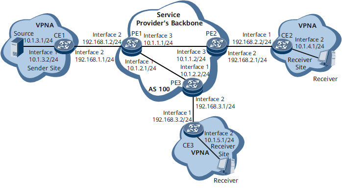
A next-generation multicast virtual private network (NG MVPN) is deployed on the service provider's backbone network to solve multicast service issues related to traffic congestion, transmission reliability, and data security. On the network shown in Figure 1, Resource Reservation Protocol-Traffic Engineering (RSVP-TE) tunnels have been deployed to carry BGP/MPLS IP VPN services. The service provider wants to provide MVPN services for users based on the existing network. To meet this requirement, configure an intra-AS NG MVPN to carry multicast traffic over an RSVP-TE point-to-multipoint (P2MP) LSP.

Configuration Roadmap
The configuration roadmap is as follows:
Configure BGP/MPLS IP VPN and ensure that unicast VPN services are properly transmitted.
Enable P2MP TE globally and configure a P2MP TE template on each provider edge (PE) so that the PEs can use RSVP-TE to establish a P2MP LSP.
Establish BGP MVPN peer relationships between the PEs so that the PEs can use BGP to exchange BGP A-D and BGP C-multicast routes.
Configure PE1 to use RSVP-TE to establish an Inclusive-Provider Multicast Service Interface (I-PMSI) tunnel so that an RSVP-TE P2MP LSP can be triggered.
Configure PIM on the PE interfaces bound to VPN instances and on the customer edge (CE) interfaces connecting to PEs to allow a VPN multicast routing table to be established to guide multicast traffic forwarding.
Configure IGMP on the interfaces connecting a multicast device to a user network segment to allow the device to manage multicast group members on the network segment.
Data Preparation
To complete the configuration, you need the following data:
IS-IS process on the public network (process 1) in a Level-2 area; System IDs of PE1, PE2, and PE3 (10.0000.0000.0001.00, 10.0000.0000.0002.00, and 10.0000.0000.0003.00)
- VPN instance name on PE1, PE2, and PE3: VPNA
Table 1 Data preparation Device Name
IP Address of Loopback 1
MPLS LSR ID
MVPN ID
RD
VPN-Target
AS Number
CE1
1.1.1.1
-
-
-
-
AS65001
PE1
2.2.2.2
2.2.2.2
2.2.2.2
200:1
3:3 4:4
AS100
PE2
3.3.3.3
3.3.3.3
3.3.3.3
300:1
3:3
AS100
PE3
4.4.4.4
4.4.4.4
4.4.4.4
400:1
4:4
AS100
CE2
5.5.5.5
-
-
-
-
AS65002
CE3
6.6.6.6
-
-
-
-
AS65003
Procedure
- Configure BGP/MPLS IP VPN.
- Enable P2MP TE globally and configure a P2MP TE template.
# Configure PE1.
[~PE1] mpls
[*PE1-mpls] mpls te p2mp-te
[*PE1-mpls] quit
[*PE1] mpls te leaf-list leaf1
[*PE1-mpls-te-leaf-list-leaf1] destination 3.3.3.3
[*PE1-mpls-te-leaf-list-leaf1-destination-3.3.3.3] path explicit-path pe1tope2
[*PE1-mpls-te-leaf-list-leaf1-destination-3.3.3.3] quit
[*PE1-mpls-te-leaf-list-leaf1] destination 4.4.4.4
[*PE1-mpls-te-leaf-list-leaf1-destination-4.4.4.4] path explicit-path pe1tope3
[*PE1-mpls-te-leaf-list-leaf1-destination-4.4.4.4] quit
[*PE1-mpls-te-leaf-list-leaf1] quit
[*PE1] mpls te p2mp-template t1
[*PE1-te-p2mp-template-t1] leaf-list leaf1
[*PE1-te-p2mp-template-t1] quit
[*PE1] commit
# Configure PE2.
[~PE2] mpls
[*PE2-mpls] mpls te p2mp-te
[*PE2-mpls] quit
[*PE2] commit
# Configure PE3.
[~PE3] mpls
[*PE3-mpls] mpls te p2mp-te
[*PE3-mpls] quit
[*PE3] commit
- Establish a BGP MVPN peer relationship between the PEs.
# Configure PE1.
[~PE1] bgp 100
[*PE1-bgp] ipv4-family mvpn
[*PE1-bgp-af-mvpn] peer 3.3.3.3 enable
[*PE1-bgp-af-mvpn] peer 4.4.4.4 enable
[*PE1-bgp-af-mvpn] quit
[*PE1-bgp] quit
[*PE1] commit
# Configure PE2.
[~PE2] bgp 100
[*PE2-bgp] ipv4-family mvpn
[*PE2-bgp-af-mvpn] peer 2.2.2.2 enable
[*PE2-bgp-af-mvpn] quit
[*PE2-bgp] quit
[*PE2] commit
# Configure PE3.
[~PE3] bgp 100
[*PE3-bgp] ipv4-family mvpn
[*PE3-bgp-af-mvpn] peer 2.2.2.2 enable
[*PE3-bgp-af-mvpn] quit
[*PE3-bgp] quit
[*PE3] commit
After the configurations are complete, run the display bgp mvpn all peer command on the PEs. The command output shows that PE1 has established a BGP MVPN peer relationship with PE2 and PE3. The following example uses the command output on PE1:
[~PE1] display bgp mvpn all peer BGP local router ID : 10.1.2.1 Local AS number : 100 Total number of peers : 2 Peers in established state : 2 Peer V AS MsgRcvd MsgSent OutQ Up/Down State PrefRcv 3.3.3.3 4 100 375 380 0 00:21:20 Established 1 4.4.4.4 4 100 358 364 0 00:14:23 Established 1 - Configure each PE to use RSVP-TE to establish an I-PMSI tunnel.
# Configure PE1.
[~PE1] multicast mvpn 2.2.2.2
[*PE1] ip vpn-instance VPNA
[*PE1-vpn-instance-VPNA] ipv4-family
[*PE1-vpn-instance-VPNA-af-ipv4] multicast routing-enable
[*PE1-vpn-instance-VPNA-af-ipv4] mvpn
[*PE1-vpn-instance-VPNA-af-ipv4-mvpn] sender-enable
[*PE1-vpn-instance-VPNA-af-ipv4-mvpn] c-multicast signaling bgp
[*PE1-vpn-instance-VPNA-af-ipv4-mvpn] ipmsi-tunnel
[*PE1-vpn-instance-VPNA-af-ipv4-mvpn-ipmsi] mpls te
[*PE1-vpn-instance-VPNA-af-ipv4-mvpn-ipmsi-mpls-te] p2mp-template t1
[*PE1-vpn-instance-VPNA-af-ipv4-mvpn-ipmsi-mpls-te] quit
[*PE1-vpn-instance-VPNA-af-ipv4-mvpn-ipmsi] quit
[*PE1-vpn-instance-VPNA-af-ipv4-mvpn] quit
[*PE1-vpn-instance-VPNA-af-ipv4] quit
[*PE1-vpn-instance-VPNA] quit
[*PE1] commit
# Configure PE2.
[~PE2] multicast mvpn 3.3.3.3
[*PE2] ip vpn-instance VPNA
[*PE2-vpn-instance-VPNA] ipv4-family
[*PE2-vpn-instance-VPNA-af-ipv4] multicast routing-enable
[*PE2-vpn-instance-VPNA-af-ipv4] mvpn
[*PE2-vpn-instance-VPNA-af-ipv4-mvpn] c-multicast signaling bgp
[*PE2-vpn-instance-VPNA-af-ipv4-mvpn] quit
[*PE2-vpn-instance-VPNA-af-ipv4] quit
[*PE2-vpn-instance-VPNA] quit
[*PE2] commit
# Configure PE3.
[~PE3] multicast mvpn 4.4.4.4
[*PE3] ip vpn-instance VPNA
[*PE3-vpn-instance-VPNA] ipv4-family
[*PE3-vpn-instance-VPNA-af-ipv4] multicast routing-enable
[*PE3-vpn-instance-VPNA-af-ipv4] mvpn
[*PE3-vpn-instance-VPNA-af-ipv4-mvpn] c-multicast signaling bgp
[*PE3-vpn-instance-VPNA-af-ipv4-mvpn] quit
[*PE3-vpn-instance-VPNA-af-ipv4] quit
[*PE3-vpn-instance-VPNA] quit
[*PE3] commit
After the configurations are complete, run the display mvpn vpn-instance ipmsi command on the PEs to check I-PMSI tunnel information. The following example uses the command output on PE1:
[~PE1] display mvpn vpn-instance VPNA ipmsi
MVPN local I-PMSI information for VPN-Instance: VPNA
Tunnel type: RSVP-TE P2MP LSP
Tunnel state: Up
P2MP ID: 0x2020202
Tunnel ID: 32801
Extended tunnel ID: 2.2.2.2
Root: 2.2.2.2 (local)
Leaf:
  1: 3.3.3.3
  2: 4.4.4.4
The command output shows that an RSVP-TE P2MP LSP has been established, with PE1 as the root node and PE2 and PE3 as leaf nodes.
- Configure PIM.
# Configure PE1.
[*PE1] interface gigabitethernet0/1/1
[*PE1-GigabitEthernet0/1/1] pim sm
[*PE1-GigabitEthernet0/1/1] quit
[*PE1] commit
# Configure CE1.
[~CE1] multicast routing-enable
[*CE1] interface gigabitethernet0/1/0
[*CE1-GigabitEthernet0/1/0] pim sm
[*CE1-GigabitEthernet0/1/0] quit
[*CE1] interface gigabitethernet0/1/1
[*CE1-GigabitEthernet0/1/1] pim sm
[*CE1-GigabitEthernet0/1/1] quit
[*CE1] commit
# Configure PE2.
[*PE2] interface gigabitethernet0/1/1
[*PE2-GigabitEthernet0/1/1] pim sm
[*PE2-GigabitEthernet0/1/1] quit
[*PE2] commit
# Configure CE2.
[~CE2] multicast routing-enable
[*CE2] interface gigabitethernet0/1/0
[*CE2-GigabitEthernet0/1/0] pim sm
[*CE2-GigabitEthernet0/1/0] quit
[*CE2] interface gigabitethernet0/1/1
[*CE2-GigabitEthernet0/1/1] pim sm
[*CE2-GigabitEthernet0/1/1] quit
[*CE2] commit
# Configure PE3.
[*PE3] interface gigabitethernet0/1/1
[*PE3-GigabitEthernet0/1/1] pim sm
[*PE3-GigabitEthernet0/1/1] quit
[*PE3] commit
# Configure CE3.
[~CE3] multicast routing-enable
[*CE3] interface gigabitethernet0/1/0
[*CE3-GigabitEthernet0/1/0] pim sm
[*CE3-GigabitEthernet0/1/0] quit
[*CE3] interface gigabitethernet0/1/1
[*CE3-GigabitEthernet0/1/1] pim sm
[*CE3-GigabitEthernet0/1/1] quit
[*CE3] commit
- Configure IGMP and IGMP version 3.
# Configure CE2.
[~CE2] interface gigabitethernet0/1/1
[*CE2-GigabitEthernet0/1/1] pim sm
[*CE2-GigabitEthernet0/1/1] igmp enable
[*CE2-GigabitEthernet0/1/1] igmp version 3
[*CE2-GigabitEthernet0/1/1] quit
[*CE2] commit
# Configure CE3.
[~CE3] interface gigabitethernet0/1/1
[*CE3-GigabitEthernet0/1/1] pim sm
[*CE3-GigabitEthernet0/1/1] igmp enable
[*CE3-GigabitEthernet0/1/1] igmp version 3
[*CE3-GigabitEthernet0/1/1] quit
[*CE3] commit
- Verify the configuration.
After the configurations are complete, NG MVPN functions have been configured. If CE2 or CE3 has access users, CE1 can use the BGP/MPLS IP VPN to forward multicast data to the users. Configure users on CE2 or CE3 to send IGMPv3 Report messages and the multicast source 10.1.3.1 to send multicast data. Then, check multicast routing entries to verify whether the NG MVPN is configured successfully.
Run the display pim routing-table command on CE2, CE3, and CE1 to check the PIM routing table. Run the display pim vpn-instance routing-table command on PE2, PE3, and PE1 to check the PIM routing table of the VPN instance.
[~CE2] display pim routing-table
 VPN-Instance: public net
 Total 0 (*, G) entry; 1 (S, G) entry

 (10.1.3.1, 225.1.1.1)
     RP: NULL
     Protocol: pim-sm, Flag: SPT SG_RCVR ACT
     UpTime: 08:48:25
     Upstream interface: GigabitEthernet0/1/0, Refresh time: 08:48:25
         Upstream neighbor: 192.168.2.1
         RPF prime neighbor: 192.168.2.1
     Downstream interface(s) information:
     Total number of downstreams: 1
        1: GigabitEthernet0/1/1
             Protocol: igmp, UpTime: 08:48:25, Expires: -
[~CE3] display pim routing-table
 VPN-Instance: public net
 Total 0 (*, G) entry; 1 (S, G) entry

 (10.1.3.1, 226.1.1.1)
     RP: NULL
     Protocol: pim-sm, Flag: SPT SG_RCVR ACT
     UpTime: 02:02:06
     Upstream interface: GigabitEthernet0/1/0, Refresh time: 02:02:06
         Upstream neighbor: 192.168.3.1
         RPF prime neighbor: 192.168.3.1
     Downstream interface(s) information:
     Total number of downstreams: 1
        1: GigabitEthernet0/1/1
             Protocol: igmp, UpTime: 02:02:06, Expires: -
[~PE2] display pim vpn-instance VPNA routing-table
 VPN-Instance: VPNA
 Total 0 (*, G) entry; 1 (S, G) entry

 (10.1.3.1, 225.1.1.1)
     RP: NULL
     Protocol: pim-sm, Flag: SPT ACT
     UpTime: 00:05:16
     Upstream interface: through-BGP, Refresh time: 00:05:16
         Upstream neighbor: 2.2.2.2
         RPF prime neighbor: 2.2.2.2
     Downstream interface(s) information:
     Total number of downstreams: 1
        1: GigabitEthernet0/1/1
             Protocol: pim-sm, UpTime: 00:05:16, Expires: 00:03:16
[~PE3] display pim vpn-instance VPNA routing-table
 VPN-Instance: VPNA
 Total 0 (*, G) entry; 1 (S, G) entry

 (10.1.3.1, 226.1.1.1)
     RP: NULL
     Protocol: pim-sm, Flag: SPT ACT
     UpTime: 00:08:08
     Upstream interface: through-BGP, Refresh time: 00:08:08
         Upstream neighbor: 2.2.2.2
         RPF prime neighbor: 2.2.2.2
     Downstream interface(s) information:
     Total number of downstreams: 1
        1: GigabitEthernet0/1/1
             Protocol: pim-sm, UpTime: 00:08:08, Expires: 00:03:24
[~PE1] display pim vpn-instance VPNA routing-table
 VPN-Instance: VPNA
 Total 0 (*, G) entry; 2 (S, G) entries

 (10.1.3.1, 225.1.1.1)
     RP: NULL
     Protocol: pim-sm, Flag: SPT SG_RCVR ACT
     UpTime: 00:01:00
     Upstream interface: GigabitEthernet0/1/1, Refresh time: 00:01:00
         Upstream neighbor: 192.168.1.1
         RPF prime neighbor: 192.168.1.1
     Downstream interface(s) information:
     Total number of downstreams: 1
        1: pseudo
             Protocol: BGP, UpTime: 00:01:00, Expires: -

 (10.1.3.1, 226.1.1.1)
     RP: NULL
     Protocol: pim-sm, Flag: SPT SG_RCVR ACT
     UpTime: 00:01:45
     Upstream interface: GigabitEthernet0/1/1, Refresh time: 00:01:45
         Upstream neighbor: 192.168.1.1
         RPF prime neighbor: 192.168.1.1
     Downstream interface(s) information:
     Total number of downstreams: 1
        1: pseudo
             Protocol: BGP, UpTime: 00:02:54, Expires: -
[~CE1] display pim routing-table
 VPN-Instance: public net
 Total 0 (*, G) entry; 2 (S, G) entries

 (10.1.3.1, 225.1.1.1)
     RP: NULL
     Protocol: pim-sm, Flag: SPT LOC ACT
     UpTime: 00:08:39
     Upstream interface: GigabitEthernet0/1/0, Refresh time: 00:08:39
         Upstream neighbor: NULL
         RPF prime neighbor: NULL
     Downstream interface(s) information:
     Total number of downstreams: 1
        1: GigabitEthernet0/1/1
             Protocol: pim-sm, UpTime: 00:08:39, Expires: 00:02:51

 (10.1.3.1, 226.1.1.1)
     RP: NULL
     Protocol: pim-sm, Flag: SPT LOC ACT
     UpTime: 00:09:24
     Upstream interface: GigabitEthernet0/1/0, Refresh time: 00:09:24
         Upstream neighbor: NULL
         RPF prime neighbor: NULL
     Downstream interface(s) information:
     Total number of downstreams: 1
        1: GigabitEthernet0/1/1
             Protocol: pim-sm, UpTime: 00:09:24, Expires: 00:03:08
The command outputs show that CE1 connecting to the multicast source has received PIM Join messages from CE2 and CE3 connecting to multicast receivers and that CE1 has generated PIM routing entries.
Configuration Files
CE1 configuration file
#
sysname CE1
#
multicast routing-enable
#
interface GigabitEthernet0/1/0
 undo shutdown
 ip address 10.1.3.2 255.255.255.0
 pim sm
#
interface GigabitEthernet0/1/1
 undo shutdown
 ip address 192.168.1.1 255.255.255.0
 pim sm
#
interface LoopBack1
 ip address 1.1.1.1 255.255.255.255
#
bgp 65001
 peer 192.168.1.2 as-number 100
 #
 ipv4-family unicast
  undo synchronization
  import-route direct
  peer 192.168.1.2 enable
#
return
PE1 configuration file
#
sysname PE1
#
multicast mvpn 2.2.2.2
#
ip vpn-instance VPNA
 ipv4-family
  route-distinguisher 200:1
  apply-label per-instance
  tnl-policy p1
  vpn-target 3:3 export-extcommunity
  vpn-target 4:4 export-extcommunity
  vpn-target 3:3 import-extcommunity
  vpn-target 4:4 import-extcommunity
  multicast routing-enable
  mvpn
   sender-enable
   c-multicast signaling bgp
   ipmsi-tunnel
    mpls te
     p2mp-template t1
#
mpls lsr-id 2.2.2.2
mpls
 mpls te
 mpls te p2mp-te
 mpls rsvp-te
 mpls te cspf
#
explicit-path pe1tope2
 next hop 10.1.1.2
 next hop 3.3.3.3
#
explicit-path pe1tope3
 next hop 10.1.2.2
 next hop 4.4.4.4
#
mpls te leaf-list leaf1
 destination 3.3.3.3
  path explicit-path pe1tope2
 destination 4.4.4.4
  path explicit-path pe1tope3
#
mpls te p2mp-template t1
 leaf-list leaf1
#
isis 1
 is-level level-2
 cost-style wide
 network-entity 10.0000.0000.0001.00
 traffic-eng level-2
#
interface GigabitEthernet0/1/0
 undo shutdown
 ip address 10.1.2.1 255.255.255.0
 isis enable 1
 mpls
 mpls te
 mpls rsvp-te
#
interface GigabitEthernet0/1/1
 undo shutdown
 ip binding vpn-instance VPNA
 ip address 192.168.1.2 255.255.255.0
 pim sm
#
interface GigabitEthernet0/1/2
 undo shutdown
 ip address 10.1.1.1 255.255.255.0
 isis enable 1
 mpls
 mpls te
 mpls rsvp-te
#
interface LoopBack1
 ip address 2.2.2.2 255.255.255.255
 isis enable 1
#
interface Tunnel10
 ip address unnumbered interface LoopBack1
 tunnel-protocol mpls te
 destination 3.3.3.3
 mpls te tunnel-id 100
 mpls te path explicit-path pe1tope2
 mpls te reserved-for-binding
#
interface Tunnel11
 ip address unnumbered interface LoopBack1
 tunnel-protocol mpls te
 destination 4.4.4.4
 mpls te tunnel-id 200
 mpls te path explicit-path pe1tope3
 mpls te reserved-for-binding
#
bgp 100
 peer 3.3.3.3 as-number 100
 peer 3.3.3.3 connect-interface LoopBack1
 peer 4.4.4.4 as-number 100
 peer 4.4.4.4 connect-interface LoopBack1
 #
 ipv4-family unicast
  undo synchronization
  peer 3.3.3.3 enable
  peer 4.4.4.4 enable
 #
 ipv4-family vpnv4
  policy vpn-target
  peer 3.3.3.3 enable
  peer 4.4.4.4 enable
 #
 ipv4-family mvpn
  policy vpn-target
  peer 3.3.3.3 enable
  peer 4.4.4.4 enable
 #
 ipv4-family vpn-instance VPNA
  import-route direct
  peer 192.168.1.1 as-number 65001
#
tunnel-policy p1
 tunnel binding destination 3.3.3.3 te Tunnel10 down-switch
 tunnel binding destination 4.4.4.4 te Tunnel11 down-switch
#
return
CE2 configuration file
#
sysname CE2
#
multicast routing-enable
#
interface GigabitEthernet0/1/0
 undo shutdown
 ip address 192.168.2.2 255.255.255.0
 pim sm
#
interface GigabitEthernet0/1/1
 undo shutdown
 ip address 10.1.4.1 255.255.255.0
 pim sm
 igmp enable
 igmp version 3
#
interface LoopBack1
 ip address 5.5.5.5 255.255.255.255
#
bgp 65002
 peer 192.168.2.1 as-number 100
 #
 ipv4-family unicast
  undo synchronization
  import-route direct
  peer 192.168.2.1 enable
#
return
PE2 configuration file
#
sysname PE2
#
multicast mvpn 3.3.3.3
#
ip vpn-instance VPNA
 ipv4-family
  route-distinguisher 300:1
  apply-label per-instance
  tnl-policy p1
  vpn-target 3:3 export-extcommunity
  vpn-target 3:3 import-extcommunity
  multicast routing-enable
  mvpn
   c-multicast signaling bgp
#
mpls lsr-id 3.3.3.3
mpls
 mpls te
 mpls te p2mp-te
 mpls rsvp-te
 mpls te cspf
#
explicit-path pe2tope1
 next hop 10.1.1.1
 next hop 2.2.2.2
#
isis 1
 is-level level-2
 cost-style wide
 network-entity 10.0000.0000.0002.00
 traffic-eng level-2
#
interface GigabitEthernet0/1/1
 undo shutdown
 ip binding vpn-instance VPNA
 ip address 192.168.2.1 255.255.255.0
 pim sm
#
interface GigabitEthernet0/1/2
 undo shutdown
 ip address 10.1.1.2 255.255.255.0
 isis enable 1
 mpls
 mpls te
 mpls rsvp-te
#
interface LoopBack1
 ip address 3.3.3.3 255.255.255.255
 isis enable 1
#
interface Tunnel10
 ip address unnumbered interface LoopBack1
 tunnel-protocol mpls te
 destination 2.2.2.2
 mpls te tunnel-id 100
 mpls te path explicit-path pe2tope1
 mpls te reserved-for-binding
#
bgp 100
 router-id 3.3.3.3
 peer 2.2.2.2 as-number 100
 peer 2.2.2.2 connect-interface LoopBack1
 #
 ipv4-family unicast
  undo synchronization
  peer 2.2.2.2 enable
 #
 ipv4-family vpnv4
  policy vpn-target
  peer 2.2.2.2 enable
 #
 ipv4-family mvpn
  policy vpn-target
  peer 2.2.2.2 enable
 #
 ipv4-family vpn-instance VPNA
  import-route direct
  peer 192.168.2.2 as-number 65002
#
tunnel-policy p1
 tunnel binding destination 2.2.2.2 te Tunnel10 down-switch
#
return
CE3 configuration file
#
sysname CE3
#
multicast routing-enable
#
interface GigabitEthernet0/1/0
 undo shutdown
 ip address 192.168.3.2 255.255.255.0
 pim sm
#
interface GigabitEthernet0/1/1
 undo shutdown
 ip address 10.1.5.1 255.255.255.0
 pim sm
 igmp enable
 igmp version 3
#
interface LoopBack1
 ip address 6.6.6.6 255.255.255.255
#
bgp 65003
 peer 192.168.3.1 as-number 100
 #
 ipv4-family unicast
  undo synchronization
  import-route direct
  peer 192.168.3.1 enable
#
return
PE3 configuration file
#
sysname PE3
#
multicast mvpn 4.4.4.4
#
ip vpn-instance VPNA
 ipv4-family
  route-distinguisher 400:1
  apply-label per-instance
  tnl-policy p1
  vpn-target 4:4 export-extcommunity
  vpn-target 4:4 import-extcommunity
  multicast routing-enable
  mvpn
   c-multicast signaling bgp
#
mpls lsr-id 4.4.4.4
mpls
 mpls te
 mpls te p2mp-te
 mpls rsvp-te
 mpls te cspf
#
explicit-path pe3tope1
 next hop 10.1.2.1
 next hop 2.2.2.2
#
isis 1
 is-level level-2
 cost-style wide
 network-entity 10.0000.0000.0003.00
 traffic-eng level-2
#
interface GigabitEthernet0/1/0
 undo shutdown
 ip address 10.1.2.2 255.255.255.0
 isis enable 1
 mpls
 mpls te
 mpls rsvp-te
#
interface GigabitEthernet0/1/1
 undo shutdown
 ip binding vpn-instance VPNA
 ip address 192.168.3.1 255.255.255.0
 pim sm
#
interface LoopBack1
 ip address 4.4.4.4 255.255.255.255
 isis enable 1
#
interface Tunnel10
 ip address unnumbered interface LoopBack1
 tunnel-protocol mpls te
 destination 2.2.2.2
 mpls te tunnel-id 100
 mpls te path explicit-path pe3tope1
 mpls te reserved-for-binding
#
bgp 100
 router-id 4.4.4.4
 peer 2.2.2.2 as-number 100
 peer 2.2.2.2 connect-interface LoopBack1
 #
 ipv4-family unicast
  undo synchronization
  peer 2.2.2.2 enable
 #
 ipv4-family vpnv4
  policy vpn-target
  peer 2.2.2.2 enable
 #
 ipv4-family mvpn
  policy vpn-target
  peer 2.2.2.2 enable
 #
 ipv4-family vpn-instance VPNA
  import-route direct
  peer 192.168.3.2 as-number 65003
#
tunnel-policy p1
 tunnel binding destination 2.2.2.2 te Tunnel10 down-switch
#
return