Example for Enabling the Highest IP Address to Be Selected as the UMH on an NG MVPN
This section provides an example for enabling the highest IP address to be selected as the UMH on an NG MVPN.
Networking Requirements
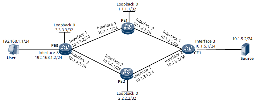
On an NG MVPN, when multiple sender PEs exist, receiver PEs select routes based on preferred unicast routes by default. On the network shown in Figure 1, the receiver PE is PE3, and the sender PEs are PE1 and PE2. By default, the path to the source that PE3 selects based on preferential unicast routes is PE3-PE1-CE1. If the system is enabled to select the highest IP address as the UMH on PE3, the path selected is PE3-PE2-CE1.

Configuration Roadmap
The configuration roadmap is as follows:
Configure BGP/MPLS IP VPN and ensure that unicast VPN services are properly transmitted. (In this example, ensure that the source and user can communicate.)
Enable mLDP on all PEs globally and ensure that the PEs can use mLDP to establish P2MP tunnels.
Enable all PEs to establish BGP MVPN peer relationships and configure BGP to transmit A-D and C-multicast routes.
Configure PE1 and PE2 to use mLDP to establish an I-PMSI tunnel so that an mLDP P2MP LSP can be triggered.
Configure PIM on PE1 and PE2 interfaces bound to VPN instances and on CE1 interfaces connecting to PEs to allow a VPN multicast routing table to be established to guide multicast traffic forwarding.
Enable the highest IP address to be selected as the UMH in the VPN instance IPv4 address family MVPN view of PE3.
Configure IGMP on the interfaces connecting a multicast device to a user network segment to allow the device to manage multicast group members on the network segment.
Data Preparation
To complete the configuration, you need the following data:
Public network OSPF process ID: 1; area ID: 0
VPN instance name on PE1, PE2, and PE3: VPNA (other data is shown in Figure 1)
Procedure
- Configure BGP/MPLS IP VPN.
- Enable mLDP globally.
# Configure PE1.
[~PE1] mpls ldp
[*PE1-mpls-ldp] mldp p2mp
[*PE1-mpls-ldp] commit
[~PE1-mpls-ldp] quit
# Configure PE2.
[~PE2] mpls ldp
[*PE2-mpls-ldp] mldp p2mp
[*PE2-mpls-ldp] commit
[~PE2-mpls-ldp] quit
# Configure PE3.
[~PE3] mpls ldp
[*PE3-mpls-ldp] mldp p2mp
[*PE3-mpls-ldp] commit
[~PE3-mpls-ldp] quit
- Establish a BGP MVPN peer relationship between the PEs.
# Configure PE1.
[~PE1] bgp 100
[*PE1-bgp] ipv4-family mvpn
[*PE1-bgp-af-mvpn] peer 3.3.3.3 enable
[*PE1-bgp-af-mvpn] commit
[~PE1-bgp-af-mvpn] quit
[~PE1-bgp] quit
# Configure PE2.
[~PE2] bgp 100
[*PE2-bgp] ipv4-family mvpn
[*PE2-bgp-af-mvpn] peer 3.3.3.3 enable
[*PE2-bgp-af-mvpn] commit
[~PE2-bgp-af-mvpn] quit
[~PE2-bgp] quit
# Configure PE3.
[~PE3] bgp 100
[*PE3-bgp] ipv4-family mvpn
[*PE3-bgp-af-mvpn] peer 1.1.1.1 enable
[*PE3-bgp-af-mvpn] peer 2.2.2.2 enable
[*PE3-bgp-af-mvpn] commit
[~PE3-bgp-af-mvpn] quit
[~PE3-bgp] quit
After the configuration is complete, run the display bgp mvpn all peer command on the PEs. The command output shows that PE1 has established a BGP MVPN peer relationship with PE2 and PE3. The following example uses the command output on PE3.
[~PE3] display bgp mvpn all peer BGP local router ID : 3.3.3.3 Local AS number : 100 Total number of peers : 2 Peers in established state : 2 Peer V AS MsgRcvd MsgSent OutQ Up/Down State PrefRcv 1.1.1.1 4 100 87 89 0 01:10:28 Established 0 2.2.2.2 4 100 87 88 0 01:09:36 Established 0 - Configure each PE to use mLDP to establish an I-PMSI tunnel.
# Configure PE1.
[~PE1] multicast mvpn 1.1.1.1
[*PE1] ip vpn-instance VPNA
[*PE1-vpn-instance-VPNA] ipv4-family
[*PE1-vpn-instance-VPNA-af-ipv4] multicast routing-enable
[*PE1-vpn-instance-VPNA-af-ipv4] mvpn
[*PE1-vpn-instance-VPNA-af-ipv4-mvpn] sender-enable
[*PE1-vpn-instance-VPNA-af-ipv4-mvpn] c-multicast signaling bgp
[*PE1-vpn-instance-VPNA-af-ipv4-mvpn] rpt-spt mode
[*PE1-vpn-instance-VPNA-af-ipv4-mvpn] ipmsi-tunnel
[*PE1-vpn-instance-VPNA-af-ipv4-mvpn-ipmsi] mldp
[*PE1-vpn-instance-VPNA-af-ipv4-mvpn-ipmsi] quit
[*PE1-vpn-instance-VPNA-af-ipv4-mvpn] quit
[*PE1-vpn-instance-VPNA-af-ipv4] quit
[*PE1-vpn-instance-VPNA] quit
[*PE1] commit
# Configure PE2.
[~PE2] multicast mvpn 2.2.2.2
[*PE2] ip vpn-instance VPNA
[*PE2-vpn-instance-VPNA] ipv4-family
[*PE2-vpn-instance-VPNA-af-ipv4] multicast routing-enable
[*PE2-vpn-instance-VPNA-af-ipv4] mvpn
[*PE2-vpn-instance-VPNA-af-ipv4-mvpn] sender-enable
[*PE2-vpn-instance-VPNA-af-ipv4-mvpn] c-multicast signaling bgp
[*PE2-vpn-instance-VPNA-af-ipv4-mvpn] rpt-spt mode
[*PE2-vpn-instance-VPNA-af-ipv4-mvpn] ipmsi-tunnel
[*PE2-vpn-instance-VPNA-af-ipv4-mvpn-ipmsi] mldp
[*PE2-vpn-instance-VPNA-af-ipv4-mvpn-ipmsi] quit
[*PE2-vpn-instance-VPNA-af-ipv4-mvpn] quit
[*PE2-vpn-instance-VPNA-af-ipv4] quit
[*PE2-vpn-instance-VPNA] quit
[*PE2] commit
# Configure PE3.
[~PE3] multicast mvpn 3.3.3.3
[*PE3] ip vpn-instance VPNA
[*PE3-vpn-instance-VPNA] ipv4-family
[*PE3-vpn-instance-VPNA-af-ipv4] multicast routing-enable
[*PE3-vpn-instance-VPNA-af-ipv4] mvpn
[*PE3-vpn-instance-VPNA-af-ipv4-mvpn] c-multicast signaling bgp
[*PE3-vpn-instance-VPNA-af-ipv4-mvpn] rpt-spt mode
[*PE3-vpn-instance-VPNA-af-ipv4-mvpn] quit
[*PE3-vpn-instance-VPNA-af-ipv4] quit
[*PE3-vpn-instance-VPNA] quit
[*PE3] commit
After the configurations are complete, run the display mvpn vpn-instance ipmsi command on the PEs to check I-PMSI tunnel information. The following example uses the command output on PE3.
[~PE3] display mvpn vpn-instance VPNA ipmsi
MVPN local I-PMSI information for VPN-Instance: VPNA
Tunnel type: mLDP P2MP LSP
Tunnel state: --
Root-ip: 1.1.1.1
Opaque value: 0x01000400008001
Root: 1.1.1.1 Leaf:
  1: 3.3.3.3 (local)

Tunnel type: mLDP P2MP LSP
Tunnel state: --
Root-ip: 2.2.2.2
Opaque value: 0x01000400008001
Root: 2.2.2.2 Leaf:   1: 3.3.3.3 (local)
The command outputs show that two mLDP P2MP LSPs have been established, with PE1 and PE2 as the root nodes respectively and PE3 as the leaf node.
- Configure PIM.
# Configure PE1.
[*PE1] interface GigabitEthernet0/1/1
[*PE1-GigabitEthernet0/1/1] pim sm
[*PE1-GigabitEthernet0/1/1] quit
[*PE1] commit
# Configure PE2.
[*PE2] interface GigabitEthernet0/1/0
[*PE2-GigabitEthernet0/1/0] pim sm
[*PE2-GigabitEthernet0/1/0] quit
[*PE2] commit
# Configure PE3.
[*PE3] interface GigabitEthernet0/1/2
[*PE3-GigabitEthernet0/1/2] pim sm
[*PE3-GigabitEthernet0/1/2] quit
[*PE3] commit
# Configure CE1.
[~CE1] multicast routing-enable
[*CE1] interface GigabitEthernet0/1/0
[*CE1-GigabitEthernet0/1/0] pim sm
[*CE1-GigabitEthernet0/1/0] quit
[*CE1] interface GigabitEthernet0/1/1
[*CE1-GigabitEthernet0/1/1] pim sm
[*CE1-GigabitEthernet0/1/1] quit
[*CE1] interface GigabitEthernet0/1/2
[*CE1-GigabitEthernet0/1/2] pim sm
[*CE1-GigabitEthernet0/1/2] quit
[*CE1] commit
- Enable the highest IP address to be selected as the UMH in the VPN instance IPv4 address family MVPN view of PE3.
[*PE3] ip vpn-instance VPNA
[*PE3-vpn-instance-VPNA] ipv4-family
[*PE3-vpn-instance-VPNA-af-ipv4] mvpn
[*PE3-vpn-instance-VPNA-af-ipv4-mvpn] umh-select highest-ip
[*PE3-vpn-instance-VPNA-af-ipv4-mvpn] quit
[*PE3-vpn-instance-VPNA-af-ipv4] quit
[*PE3-vpn-instance-VPNA] quit
- Configure IGMP and IGMP version 3.
# Configure PE3.
[~PE3] interface GigabitEthernet0/1/2
[*PE3-GigabitEthernet0/1/2] igmp enable
[*PE3-GigabitEthernet0/1/2] igmp version 3
[*PE3-GigabitEthernet0/1/1] commit
[~PE3-GigabitEthernet0/1/1] quit
- Verify the configuration.
After the preceding configurations are complete, run the display ip routing-table vpn-instance VPNA command on PE3. The command output shows that the next hop of the optimal unicast path is PE1.
[~PE3] display ip routing-table vpn-instance VPNA
Route Flags: R - relay, D - download to fib, T - to vpn-instance, B - black hole route
 ------------------------------------------------------------------------------
 Routing Table : VPNA
          Destinations : 8        Routes : 8

 Destination/Mask    Proto   Pre  Cost        Flags NextHop         Interface

       10.1.2.0/24  IBGP    255  0             RD  1.1.1.1         0/1/0
       10.1.3.0/24  IBGP    255  2             RD  2.2.2.2         0/1/1
     10.1.5.0/24  IBGP    255  3             RD  1.1.1.1         0/1/0
      127.0.0.0/8   Direct  0    0             D   127.0.0.1       InLoopBack0
    192.168.1.0/24  Direct  0    0             D   192.168.1.2     0/1/2
    192.168.1.2/32  Direct  0    0             D   127.0.0.1       0/1/2
  192.168.1.255/32  Direct  0    0             D   127.0.0.1       0/1/2
255.255.255.255/32  Direct  0    0             D   127.0.0.1       InLoopBack0
Run the display pim vpn-instance VPNA routing-table command on PE3. The command output shows that the UMH of the route selected based on the highest IP address is PE2. When the source sends multicast traffic to the source group, the user can receive the multicast traffic and the traffic travels along the path PE3-PE2-CE1.
[~PE3] display pim vpn-instance VPNA routing-table
 VPN-Instance: VPNA
 Total 0 (*, G) entry; 1 (S, G) entry

 (10.1.5.2, 224.1.1.1)
     RP: NULL
     Protocol: pim-sm, Flag: SPT SG_RCVR
     UpTime: 00:22:17
     Upstream interface: through-BGP, Refresh time: 00:22:17
         Upstream neighbor: 2.2.2.2
         RPF prime neighbor: 2.2.2.2
     Downstream interface(s) information:
     Total number of downstreams: 1
        1: 0/1/2
             Protocol: static, UpTime: 00:22:17, Expires: -
Configuration Files
CE1 configuration file
#
sysname CE1
multicast routing-enable
#
interface GigabitEthernet0/1/0
 undo shutdown
 ip address 10.1.2.2 255.255.255.0
 pim sm
#
interface GigabitEthernet0/1/2
 undo shutdown
 ip address 10.1.5.1 255.255.255.0
 pim sm
#
interface GigabitEthernet0/1/1
 undo shutdown
 ip address 10.1.3.2 255.255.255.0
 pim sm
#
return
PE1 configuration file
#
sysname PE1
#
multicast mvpn 1.1.1.1
#
ip vpn-instance VPNA
 ipv4-family
  route-distinguisher 300:1
  apply-label per-instance
  vpn-target 3:3 export-extcommunity
  vpn-target 3:3 import-extcommunity
  multicast routing-enable
  mvpn
   sender-enable
   c-multicast signaling bgp
   rpt-spt mode
   ipmsi-tunnel
    mldp
#
mpls lsr-id 1.1.1.1
#
mpls
#
mldp-p2mp-tunnel p2mp-lsp
#
mpls ldp
 #
 ipv4-family
#
#
interface GigabitEthernet0/1/1
 undo shutdown
 ip binding vpn-instance VPNA
 ip address 10.1.2.1 255.255.255.0
#
interface
GigabitEthernet0/1/0
 undo shutdown
 ip address 10.1.1.1 255.255.255.0
 mpls
 mpls ldp
#
interface LoopBack0
 ip address 1.1.1.1 255.255.255.255
#
bgp 100
 peer 3.3.3.3 as-number 100
 peer 3.3.3.3 connect-interface LoopBack0
 #
 ipv4-family unicast
  undo synchronization
  peer 3.3.3.3 enable
 #
 ipv4-family mvpn
  policy vpn-target
  peer 3.3.3.3 enable
 #
 ipv4-family vpnv4
  policy vpn-target
  peer 3.3.3.3 enable
 #
 ipv4-family vpn-instance VPNA
  import-route direct
  import-route static
#
ospf 1
 area 0.0.0.0
  network 1.1.1.1 0.0.0.0
  network 10.1.1.0 0.0.0.255
#
return
PE2 configuration file
#
sysname PE2
#
multicast mvpn 2.2.2.2
#
ip vpn-instance VPNA
 ipv4-family
  route-distinguisher 300:1
  apply-label per-instance
  vpn-target 4:4 export-extcommunity
  vpn-target 4:4 import-extcommunity
  multicast routing-enable
  mvpn
   sender-enable
   c-multicast signaling bgp
   rpt-spt mode
   ipmsi-tunnel
    mldp
#
mpls lsr-id 2.2.2.2
#
mpls
#
mldp-p2mp-tunnel p2mp-lsp
#
mpls ldp
 #
 ipv4-family
#
interface GigabitEthernet0/1/1
 undo shutdown
 ip address 10.1.4.1 255.255.255.0
 mpls
 mpls ldp
#
interface
GigabitEthernet0/1/0
 undo shutdown
 ip binding vpn-instance VPNA
 ip address 10.1.3.1 255.255.255.0
 pim sm
#
interface LoopBack0
 ip address 2.2.2.2 255.255.255.255
#
bgp 100
 peer 3.3.3.3 as-number 100
 peer 3.3.3.3 connect-interface LoopBack0
 #
 ipv4-family unicast
  undo synchronization
  peer 3.3.3.3 enable
 #
 ipv4-family mvpn
  policy vpn-target
  peer 3.3.3.3 enable
 #
 ipv4-family vpnv4
  policy vpn-target
  peer 3.3.3.3 enable
 #
 ipv4-family vpn-instance VPNA
  import-route direct
  import-route static
#
ospf 1
 area 0.0.0.0
  network 2.2.2.2 0.0.0.0
  network 10.1.4.0 0.0.0.255
#
return
PE3 configuration file
#
 sysname PE3
#
multicast mvpn 3.3.3.3
#
ip vpn-instance VPNA
 ipv4-family
  route-distinguisher 400:1
  apply-label per-instance
  vpn-target 3:3 export-extcommunity
  vpn-target 4:4 export-extcommunity
  vpn-target 3:3 import-extcommunity
  vpn-target 4:4 import-extcommunity
  multicast routing-enable
  mvpn
   c-multicast signaling bgp
   rpt-spt mode
   umh-select highest-ip
#
mpls lsr-id 3.3.3.3
#
mpls
#
mpls ldp
 mldp p2mp
 #
 ipv4-family
#
interface GigabitEthernet0/1/1
 undo shutdown
 ip address 10.1.4.2 255.255.255.0
 mpls
 mpls ldp
#
interface GigabitEthernet0/1/0
 undo shutdown
 ip address 10.1.1.2 255.255.255.0
 mpls
 mpls ldp
#
interface GigabitEthernet0/1/2
 undo shutdown
 ip binding vpn-instance VPNA
 ip address 192.168.1.2 255.255.255.0
 pim sm
 igmp static-group 224.1.1.1 source 10.1.5.2
#
interface LoopBack0
 ip address 3.3.3.3 255.255.255.255
#
bgp 100
 peer 1.1.1.1 as-number 100
 peer 1.1.1.1 connect-interface LoopBack0
 peer 2.2.2.2 as-number 100
 peer 2.2.2.2 connect-interface LoopBack0
 #
 ipv4-family unicast
  undo synchronization
  peer 1.1.1.1 enable
  peer 2.2.2.2 enable
 #
 ipv4-family mvpn
  policy vpn-target
  peer 1.1.1.1 enable
  peer 2.2.2.2 enable
 #
 ipv4-family vpnv4
  policy vpn-target
  peer 1.1.1.1 enable
  peer 2.2.2.2 enable
 #
 ipv4-family vpn-instance VPNA
  network 192.168.1.0 255.255.255.0
#
ospf 1
 area 0.0.0.0
  network 3.3.3.3 0.0.0.0
  network 10.1.1.0 0.0.0.255
  network 10.1.4.0 0.0.0.255
#
return