Example for Configuring NG MVPN Extranet in the Remote Route Leaking Scenario (BAS Multicast)
This section provides an example for configuring NG MVPN extranet in the remote route leaking scenario where a source VPN instance needs to be configured on a receiver PE and multicast users access a network through BAS interfaces.
Networking Requirements
In NG MVPN scenarios, a service provider on a VPN may need to provide multicast services for users on other VPNs. NG MVPN extranet can be used to distribute multicast services between different VPNs. Users access the network through the BAS interface.
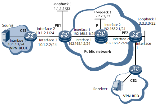
In the remote route leaking scenario of intra-AS NG MVPN shown in Figure 1, the receiver in VPN RED requires multicast data from the source in VPN BLUE. To meet this requirement, deploy NG MVPN extranet by configuring source VPN BLUE on receiver PE2. In addition, configure a multicast routing policy for VPN RED on receiver PE2 and specify in the policy that the upstream interface of the RPF route belongs to VPN BLUE.

Configuration Roadmap
The configuration roadmap is as follows:
Configure basic intra-AS NG MVPN functions.
Configure VPN BLUE with the IPv4 address family enabled on PE2.
Configure a private network RP to serve the NG MVPN extranet.
Configure a multicast routing policy for VPN RED on PE2 and specify VPN BLUE as the upstream interface of the RPF route.
Configure IPoE user access on PE2's interface connected to the multicast user side.
Data Preparation
To complete the configuration, you need the following data:
RD and VPN target of VPN BLUE: 100:1; VPN target of MVPN routes: 1:1
RD of VPN RED: 200:1; VPN targets of VPN RED: 200:1 and 100:1
Procedure
- Configure basic intra-AS NG MVPN functions.
- Configure a private network RP to serve the NG MVPN extranet.
# Configure CE1.
[~CE1] pim
[*CE1-pim] static-rp 10.1.1.1
[*CE1-pim] quit
[*CE1] commit
# Configure PE1.
[~PE1] pim vpn-instance BLUE
[*PE1-pim-BLUE] static-rp 10.1.1.1
[*PE1-pim-BLUE] quit
[*PE1] commit
# Configure PE2.
[~PE2] pim vpn-instance BLUE
[*PE2-pim-BLUE] static-rp 10.1.1.1
[*PE2-pim-BLUE] quit
[*PE2] commit
- Configure a multicast routing policy for VPN RED, specifying that the upstream interface of the RPF route selected by the PIM entry with the group address 228.1.1.0/24 belongs to VPN BLUE.
[~PE2] ip vpn-instance RED
[*PE2-vpn-instance-RED] ipv4-family
[*PE2-vpn-instance-RED-af-ipv4] mvpn
[*PE2-vpn-instance-RED-af-ipv4-mvpn] multicast extranet select-rpf vpn-instance BLUE group 228.0.0.0 24
[*PE2-vpn-instance-RED-af-ipv4-mvpn] quit
[*PE2-vpn-instance-RED-af-ipv4] quit
[*PE2-vpn-instance-RED] quit
[*PE2] commit
- Configure user access.
# Configure PE2.
[~PE2] ip pool ipv4 bas local
[*PE2-ip-pool-vpn] vpn-instance RED
[*PE2-ip-pool-vpn] gateway 10.1.3.1 255.255.255.0
[*PE2-ip-pool-vpn] section 1 10.1.3.64 10.1.3.127
[*PE2-ip-pool-vpn] quit
[~PE2] aaa
[~PE2-aaa] authentication-scheme none
[*PE2-aaa-authen-none] authentication-mode none
[*PE2-aaa-authen-none] quit
[~PE2-aaa] accounting-scheme none
[*PE2-aaa-accounting-none] accounting-mode none
[*PE2-aaa-accounting-none] quit
[~PE2-aaa] domain vpn
[*PE2-aaa-domain-vpn] authentication-scheme none
[*PE2-aaa-domain-vpn] accounting-scheme none
[*PE2-aaa-domain-vpn] ip-pool ipv4
[*PE2-aaa-domain-vpn] vpn-instance RED
[*PE2-aaa-domain-vpn] quit
[*PE2-aaa] quit
[*PE2] commit
[~PE2] interface GigabitEthernet0/1/0
[*PE2-GigabitEthernet0/1/0] multicast binding vpn-instance RED
[*PE2-GigabitEthernet0/1/0] pim sm
[*PE2-GigabitEthernet0/1/0] igmp enable
[*PE2-GigabitEthernet0/1/0] igmp static-group 228.0.0.1 source 10.1.1.15
[*PE2-GigabitEthernet0/1/0] quit
[~PE2] interface GigabitEthernet0/1/0.1
[*PE2-GigabitEthernet0/1/0.1] user-vlan 10
[*PE2-GigabitEthernet0/1/0.1] bas
[~PE2-GigabitEthernet0/1/0.1-bas] access-type layer2-subscriber default-domain authentication vpn
[*PE2-GigabitEthernet0/1/0.1-bas] authentication-method bind
[*PE2-GigabitEthernet0/1/0.1-bas] multicast copy by-vlan
[*PE2-GigabitEthernet0/1/0.1-bas] quit
[*PE2-GigabitEthernet0/1/0.1] quit
[*PE2] commit
# Configure CE2.
[~CE2] interface gigabitethernet 0/1/0
[*CE2-GigabitEthernet0/1/0] portswitch
[*CE2-GigabitEthernet0/1/0] port link-type trunk
[*CE2-GigabitEthernet0/1/0] port trunk allow-pass vlan 10
[*CE2-GigabitEthernet0/1/0] quit
[*CE2] interface gigabitethernet 0/1/8
[*CE2-GigabitEthernet0/1/8] portswitch
[*CE2-GigabitEthernet0/1/8] port link-type access
[*CE2-GigabitEthernet0/1/8] port default vlan 10
[*CE2-GigabitEthernet0/1/8] quit
[*CE2] commit
- Verify the configuration.
By checking the configuration, you can view that the receiver in VPN RED can receive multicast data from the source in VPN BLUE.
Run the display pim routing-table command on PE2 to check information about the PIM routing table. The following command output shows that the upstream interface of the RPF route selected by the PIM entry with the group address 228.0.0.1 belongs to VPN BLUE.
[~PE2] display pim vpn-instance RED routing-table extranet source-vpn-instance BLUE
 VPN-Instance: RED
 Total 1 (*, G) entry; 2 (S, G) entries

 Total matched 1 (*, G) entry; 1 (S, G) entry

 (*, 228.0.0.1)
     RP: 10.1.1.1
     Protocol: pim-sm, Flag: WC
     UpTime: 00:47:55
     Upstream interface: MCAST_Extranet(BLUE), Refresh time: 00:47:55
         Upstream neighbor: 1.1.1.1
         RPF prime neighbor: 1.1.1.1
     Downstream interface(s) information:
     Total number of downstreams: 1
        1: GigabitEthernet0/1/0(BAS)
             Protocol: pim-sm, UpTime: 00:47:55, Expires: 00:02:34

 (10.1.1.15, 228.0.0.1)
     RP: 10.1.1.1
     Protocol: pim-sm, Flag: SPT ACT
     UpTime: 06:18:43
     Upstream interface: MCAST_Extranet(BLUE), Refresh time: 06:18:43
         Upstream neighbor: 1.1.1.1
         RPF prime neighbor: 1.1.1.1
     Downstream interface(s) information:
     Total number of downstreams: 1
        1: GigabitEthernet0/1/0(BAS)
             Protocol: pim-sm, UpTime: 00:47:57, Expires: 00:02:32
Run the display multicast routing-table command on PE2 to check information about the multicast routing table. The following command output shows that the upstream interface of the RPF route selected by the multicast routing entry with the group address 228.0.0.1 belongs to VPN BLUE.
[~PE2] display multicast vpn-instance RED routing-table extranet source-vpn-instance BLUE
Multicast routing table of VPN instance: RED
 Total 0 (*, G) entry; 1 (S, G) entry, 1 matched

 00001: (10.1.1.15, 228.0.0.1)
       Uptime: 00:42:23
       Upstream Interface: MCAST_Extranet(BLUE)
       List of 1 downstream interface
           1: GigabitEthernet0/1/0(BAS)
Run the display multicast rpf-info command on PE2 to check the RPF routing information of source 10.1.1.2. The following command output shows that the upstream interface of the RPF route selected by the multicast routing entry with the group address 228.0.0.1 belongs to VPN BLUE.
[~PE2] display multicast vpn-instance RED rpf-info 10.1.1.15 228.0.0.1
 VPN-Instance: RED
 RPF information about source 10.1.1.15 and group 228.0.0.1
     RPF interface: MCAST_Extranet
     RPF Source VPN-Instance: BLUE
     Referenced route/mask: 10.1.1.0/24
     Referenced route type: unicast
     Route selection rule: preference-preferred
     Load splitting rule: disable
Configuration Files
PE1 configuration file
#
sysname PE1
#
multicast mvpn 1.1.1.1
#
ip vpn-instance BLUE
 ipv4-family
  route-distinguisher 100:1
  apply-label per-instance
  vpn-target 100:1 export-extcommunity
  vpn-target 100:1 import-extcommunity
  multicast routing-enable
  mvpn
   sender-enable
   c-multicast signaling bgp
   rpt-spt mode
   vpn-target 1:1 export-extcommunity
   vpn-target 1:1 import-extcommunity
   ipmsi-tunnel
    mldp
   spmsi-tunnel
    group 228.0.0.0 255.255.255.0 mldp limit 1
#
mpls lsr-id 1.1.1.1
mpls
#
mpls ldp
 mldp p2mp
#
interface GigabitEthernet0/1/0
 undo shutdown
 ip address 192.168.1.1 255.255.255.0
 mpls
 mpls ldp
#
interface GigabitEthernet0/1/8
 undo shutdown
 ip binding vpn-instance BLUE
 ip address 10.1.2.2 255.255.255.0
 pim sm
#
interface LoopBack1
 ip address 1.1.1.1 255.255.255.255
#
bgp 100
 peer 3.3.3.3 as-number 100
 peer 3.3.3.3 connect-interface LoopBack1
 #
 ipv4-family unicast
  undo synchronization
  peer 3.3.3.3 enable
 #
 ipv4-family vpnv4
  policy vpn-target
  peer 3.3.3.3 enable
 #
 ipv4-family mvpn
  policy vpn-target
  peer 3.3.3.3 enable
 #
 ipv4-family vpn-instance BLUE
  import-route ospf 2
#
ospf 1
 area 0.0.0.0
  network 1.1.1.1 0.0.0.0
  network 192.168.1.0 0.0.0.255
#
ospf 2 vpn-instance BLUE
 import-route bgp
 area 0.0.0.0
  network 10.1.2.2 0.0.0.255
#
pim vpn-instance BLUE
 static-rp 10.1.1.1
#
return
PE2 configuration file
#
sysname PE2
#
multicast routing-enable
#
multicast extranet traffic-forward type bas igmp
#
ip vpn-instance BLUE
 ipv4-family
  route-distinguisher 100:1
  apply-label per-instance
  vpn-target 100:1 export-extcommunity
  vpn-target 100:1 import-extcommunity
  multicast routing-enable
  mvpn
   vpn-target 1:1 export-extcommunity
   vpn-target 1:1 import-extcommunity
   c-multicast signaling bgp
   rpt-spt mode
#
ip vpn-instance RED
 ipv4-family
  route-distinguisher 200:1
  vpn-target 200:1 export-extcommunity
  vpn-target 200:1 import-extcommunity
  vpn-target 100:1 import-extcommunity
  multicast routing-enable
  mvpn
   multicast extranet select-rpf vpn-instance BLUE group 228.0.0.0 255.255.255.0
#
mpls lsr-id 3.3.3.3
#
mpls
#
mpls ldp
 mldp p2mp
#
ip pool ipv4 bas local
 vpn-instance RED
 gateway 10.1.3.1 255.255.255.0
 section 1 10.1.3.64 10.1.3.127
#
aaa
 #
 authentication-scheme none
  authentication-mode none
 #
 accounting-scheme none
  accounting-mode none
 #
 domain vpn
  authentication-scheme none
  accounting-scheme none
  ip-pool ipv4
  vpn-instance RED
#
interface GigabitEthernet0/1/0
 undo shutdown
 multicast binding vpn-instance RED
 pim sm
 igmp enable
 igmp static-group 228.0.0.1 source 10.1.1.15
#
interface GigabitEthernet0/1/0.1
 undo shutdown
 user-vlan 10
 bas
 #
  access-type layer2-subscriber default-domain authentication vpn
  authentication-method bind
  multicast copy by-vlan
#
interface GigabitEthernet0/1/8
 undo shutdown
 ip address 192.168.2.2 255.255.255.0
 mpls
 mpls ldp
#
interface LoopBack1
 ip address 3.3.3.3 255.255.255.255
#
bgp 100
 peer 1.1.1.1 as-number 100
 peer 1.1.1.1 connect-interface LoopBack1
 #
 ipv4-family unicast
  peer 1.1.1.1 enable
 #
 ipv4-family vpnv4
  policy vpn-target
  peer 1.1.1.1 enable
 #
 ipv4-family mvpn
  policy vpn-target
  peer 1.1.1.1 enable
 #
 ipv4-family vpn-instance BLUE
  import-route direct
  import-route ospf 2
 #
 ipv4-family vpn-instance RED
  import-route direct
  import-route ospf 2
#
ospf 1
 area 0.0.0.0
  network 3.3.3.3 0.0.0.0
  network 192.168.2.0 0.0.0.255
#
ospf 2 vpn-instance RED
 import-route bgp
 area 0.0.0.0
  network 10.1.3.0 0.0.0.255
#
pim
#
pim vpn-instance BLUE
 static-rp 10.1.1.1
#
return
CE1 configuration file
#
sysname CE1
#
multicast routing-enable
#
interface GigabitEthernet0/1/0
 undo shutdown
 ip address 10.1.1.1 255.255.255.0
 pim sm
#
interface GigabitEthernet0/1/8
 undo shutdown
 ip address 10.1.2.1 255.255.255.0
 pim sm
#
ospf 2
 area 0.0.0.0
  network 10.1.1.0 0.0.0.255
  network 10.1.2.0 0.0.0.255
#
pim
 static-rp 10.1.1.1
#
return
CE2 configuration file
#
sysname CE2
#
multicast routing-enable
#
vlan batch 10
#
igmp-snooping enable
#
vlan 10
 igmp-snooping enable
#
interface Vlanif10
 ip address 10.1.3.2 255.255.255.0
#
interface GigabitEthernet0/1/0
 undo shutdown
 portswitch
 port link-type trunk
 port trunk allow-pass vlan 10
#
interface GigabitEthernet0/1/8
 undo shutdown
 portswitch
 port link-type access
 port default vlan 10
#
ospf 2
 area 0.0.0.0
  network 10.1.3.0 0.0.0.255
#
return