Example for Configuring Association Between a Route Monitoring Group and a Dual-Device Hot Backup Module
In a dual-device hot backup scenario, if the primary link on the network side fails, the association between the service module and the route monitoring group prevents traffic overload and forwarding failures, improving user experience.
Networking Requirements
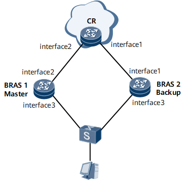
Figure 1 shows a dual-device hot backup scenario, it is required that network-side routes be added to a route monitoring group and access-side service modules be associated with the group so that the service modules perform primary/backup link switchovers upon route changes in the group to prevent traffic congestion or loss.

Interface 1, interface 2, and interface 3 in this example stand for GE 0/1/0, GE 0/1/8, and GE0/1/16.100 respectively.
Device Name |
Interface |
IP Address |
|---|---|---|
BRAS1 |
LoopBack1 |
1.1.1.1/32 |
GE 0/1/16.100 |
10.10.10.1/24 |
|
GE 0/1/8 |
10.1.2.1/24 |
|
BRAS2 |
LoopBack1 |
2.2.2.2/32 |
GE 0/1/0 |
10.1.4.1/24 |
|
GE 0/1/16.100 |
10.10.10.10/24 |
|
CR |
LoopBack1 |
3.3.3.3/32 |
GE 0/1/0 |
10.1.4.2/24 |
|
GE 0/1/8 |
10.1.2.2/24 |
Configuration Roadmap
The configuration roadmap is as follows:
Assign an IP address to each interface and configure routing protocols.
Configure a BFD session to rapidly detect faults in interfaces or links and trigger a master/backup VRRP switchover.
Configure a VRRP backup group on gigabitethernet 0/1/16.100, and configure the VRRP backup group to track the BFD session and network-side interface.
Configure an RBS and an RBP.
Configure a route monitoring group on BRAS1 and associate the route monitoring group with the dual-device hot backup module.
Data Preparation
To complete the configuration, you need the backup ID, which works together with an RBS to identify an RBP to which users belong.
Procedure
- Assign an IP address to each interface and configure device names and routing protocols.
For configuration details, see "Configuration Files" in this section.
- Configure the BFD
[~BRAS1] bfd
[*BRAS1-bfd] quit
[*BRAS1] bfd atob bind peer-ip 10.10.10.10 source-ip 10.10.10.1
[*BRAS1-bfd-session-bfd] discriminator local 2
[*BRAS1-bfd-session-bfd] discriminator remote 3
[*BRAS1-bfd-session-bfd] commit
[~BRAS1-bfd-session-bfd] quit
The configuration of BRAS2 is similar to the configuration of BRAS1. For configuration details, see "Configuration Files" in this section.
- Configure a VRRP backup group on gigabitethernet 0/1/16.100, and configure the VRRP backup group to track the BFD session and network-side interface.
[~BRAS1] interface gigabitethernet 0/1/16.100
[*BRAS1-Gigabitethernet0/1/16.100] vrrp vrid 3 virtual-ip 10.10.10.2
[*BRAS1-Gigabitethernet0/1/16.100] admin-vrrp vrid 3
[*BRAS1-Gigabitethernet0/1/16.100] vrrp vrid 3 priority 120
[*BRAS1-Gigabitethernet0/1/16.100] vrrp vrid 3 preempt-mode timer delay 1200
[*BRAS1-Gigabitethernet0/1/16.100] vrrp vrid 3 track bfd-session 2 peer
[*BRAS1-Gigabitethernet0/1/16.100] vrrp recover-delay 20
[*BRAS1-Gigabitethernet0/1/16.100] commit
[~BRAS1-Gigabitethernet0/1/16.100] quit
The configuration of BRAS2 is similar to the configuration of BRAS1. For configuration details, see "Configuration Files" in this section.
- Configure an RBS and an RBP.
# Configure an IP address for the RBS.
[~BRAS1] interface loopback1
[*BRAS1-loopback1] ip address 1.1.1.1 32
[*BRAS1-loopback1] commit
[~BRAS1-loopback1] quit
# Configure a remote backup service.
[~BRAS1] remote-backup-service rbsv8
[*BRAS1-rm-backup-srv-rbsv8] peer 2.2.2.2 source 1.1.1.1 port 55333
[*BRAS1-rm-backup-srv-rbsv8] commit
[~BRAS1-rm-backup-srv-rbsv8] quit
# Configure an RBP.
[~BRAS1] remote-backup-profile rbpv8
[*BRAS1-rm-backup-prf-rbpv8] service-type bras
[*BRAS1-rm-backup-prf-rbpv8] backup-id 1024 remote-backup-service rbsv8
[*BRAS1-rm-backup-prf-rbpv8] peer-backup hot
[*BRAS1-rm-backup-prf-rbpv8] vrrp-id 3 interface gigabitethernet 0/1/16.100
[*BRAS1-rm-backup-prf-rbpv8] commit
[~BRAS1-rm-backup-prf-rbpv8] quit
The configuration of BRAS2 is similar to the configuration of BRAS1. For configuration details, see "Configuration Files" in this section.
- Configure a route monitoring group on BRAS1 and associate the route monitoring group with the dual-device hot backup module.
[~BRAS1] ip route-monitor-group lp
[*BRAS1-route-monitor-group-lp] track ip route 10.1.2.0 24 down-weight 20
[*BRAS1-route-monitor-group-lp] monitor enable
[*BRAS1-route-monitor-group-lp] commit
[~BRAS1-route-monitor-group-lp] quit
[~BRAS1] remote-backup-service rbsv8
[*BRAS1-rm-backup-srv-rbsv8] track route-monitor-group lp switchover failure-ratio 20
[*BRAS1-rm-backup-srv-rbsv8] commit
[~BRAS1-rm-backup-srv-rbsv8] quit
- Verify the configuration.
# Run the display remote-backup-service command on BRAS1. The command output shows that the route monitoring group is associated with the dual-device hot backup module.
[~BRAS1] display remote-backup-service rbsv8
2017-12-23 11:41:50.663
----------------------------------------------------------
 Service-Index    : 1
 Service-Name     : rbsv8
 TCP-State        : Connected
 Peer-ip          : 2.2.2.2
 Source-ip        : 1.1.1.1
 TCP-Port         : 55333
 Track-BFD        : -
 SSL-Policy-Name  : --
 SSL-State        : --
 Last up time     : 2017-12-21 15:33:06
 Last down time   : 2017-12-21 16:31:10
 Last down reason : TCP closed for echo time out
 Uplink state     : 2 (1:DOWN 2:UP)
 Track-route-monitor-group lp switchover percent 20
                               TotalWeight : 0
                               DownWeight  : 0
 Domain-map-list  : --
----------------------------------------------------------
# Run the display ip route-monitor-group command on BRAS1 to view information about the route monitoring group.
[~BRAS1] display ip route-monitor-group
 Route monitor group number : 1
 Route monitor group              Total weight          Down weight        State
 lp                               10                    10                 Enabled
Configuration Files
BRAS1 configuration file
#
sysname BRAS1
#
bfd
#
bfd atob bind peer-ip 10.10.10.10 source-ip 10.10.10.1
 discriminator local 2
 discriminator remote 3
#
ip route-monitor-group lp
 track ip route 10.1.2.0 24 down-weight 20
 monitor enable
#
remote-backup-service rbsv8
 peer 2.2.2.2 source 1.1.1.1 port 55333
 track route-monitor-group lp switchover failure-ratio 20
#
remote-backup-profile rbpv8
 service-type bras
 backup-id 1024 remote-backup-service rbsv8
 peer-backup hot
 vrrp-id 3 interface GigabitEthernet0/1/16.100
#
interface GigabitEthernet0/1/8
 ip address 10.1.2.1 255.255.255.0
#
interface GigabitEthernet0/1/16.100
 vlan-type dot1q 600
 ip address 10.10.10.1 255.255.255.0
 vrrp vrid 3 virtual-ip 10.10.10.2
 admin-vrrp vrid 3
 vrrp vrid 3 priority 120
 vrrp vrid 3 preempt-mode timer delay 1200
 vrrp vrid 3 track bfd-session 2 peer
 vrrp recover-delay 20
#
interface LoopBack1
 ip address 1.1.1.1 255.255.255.255
#
ospf 4
 import-route direct
 area 0.0.0.0
  network 10.1.2.0 0.0.0.255
  network 1.1.1.0 0.0.0.255
#
return
BRAS2 configuration file
#
sysname BRAS2
#
bfd
#
bfd atob bind peer-ip 10.10.10.1 source-ip 10.10.10.10
 discriminator local 3
 discriminator remote 2
#
remote-backup-service rbsv8
 peer 1.1.1.1 source 2.2.2.2 port 55333
#
remote-backup-profile rbpv8
 service-type bras
 backup-id 1024 remote-backup-service rbsv8
 peer-backup hot
 vrrp-id 3 interface GigabitEthernet0/1/16.100
#
interface GigabitEthernet0/1/0
 ip address 10.1.4.1 255.255.255.0
#
interface GigabitEthernet0/1/16.100
 vlan-type dot1q 600
 ip address 10.10.10.10 255.255.255.0
 vrrp vrid 3 virtual-ip 10.10.10.2
 admin-vrrp vrid 3
 vrrp vrid 3 track bfd-session 3 peer
 vrrp recover-delay 20
#
interface LoopBack1
 ip address 2.2.2.2 255.255.255.255
#
ospf 4
 import-route direct
 area 0.0.0.0
  network 10.1.4.0 0.0.0.255
  network 2.2.2.0 0.0.0.255
#
return
CR configuration file
#
sysname CR
#
interface GigabitEthernet0/1/0
 ip address 10.1.4.2 255.255.255.0
#
interface GigabitEthernet0/1/8
 ip address 10.1.2.2 255.255.255.0
#
interface LoopBack1
 ip address 3.3.3.3 255.255.255.255
#
ospf 4
 import-route direct
 area 0.0.0.0
  network 10.1.4.0 0.0.0.255
  network 10.1.2.0 0.0.0.255
  network 3.3.3.0 0.0.0.255
#
return