Overview of CFM
Connectivity fault management (CFM), which provides Ethernet operation, administration and maintenance (OAM) functions, can monitor network-wide connectivity and locate connectivity faults.
Easy-to-use Ethernet techniques support good bandwidth expansibility on low-cost hardware. With these advantages, Ethernet services and structures have been widely used on enterprise networks, metropolitan area networks (MANs), and wide area networks (WANs). As Ethernet applications become increasingly popular, carriers are eager to use improved Ethernet OAM functions to maintain and operate Ethernet networks.
Figure 1 shows hierarchical Ethernet OAM for different layers of networks.
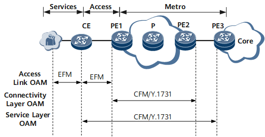
- Hierarchical Ethernet OAM provides the following functions:
IEEE 802.3ah (also known as Ethernet in the First Mile, EFM): A link-level OAM mechanism that provides continuity check, fault monitoring, remote fault notification, and remote loopback functions for the link between directly connected devices.
IEEE 802.1ag (also known as connectivity fault management, CFM): A network-level OAM mechanism that provides Ethernet OAM functions, such as continuity check (CC), loopback (LB), and linktrace (LT). CFM applies to large, end-to-end networks.
- Y.1731: An OAM protocol defined by the International Telecommunication Union-Telecommunication Standardization Sector (ITU-T), which provides fault management and performance monitoring functions in addition to the contents defined in IEEE 802.1ag. Fault management includes alarm indication signal (AIS), remote defect indication (RDI), locked signal (LCK), test signal, maintenance communication channel (MCC), experimental (EXP) OAM, and vendor specific (VSP) OAM. Performance monitoring includes frame loss measurement (LM) and delay measurement (DM).
Basic Concepts
Maintenance domain (MD)
MDs are discrete areas within which connectivity fault detection is enabled. The boundary of an MD is determined by maintenance association end points (MEPs) configured on interfaces. An MD is identified by an MD name.
To help locate faults, MDs are separated into eight levels, which are numbered 0 through 7. A larger value indicates a higher level and a larger coverage area. One MD can be tangential to another MD. Tangential MDs share a single device, which has one interface in each of the MDs. A lower-level MD can be nested in a higher-level MD, but a higher-level MD cannot be nested in a lower-level MD. An MD must be fully nested in another MD, and the two MDs cannot simply overlap.
Default MD
According to IEEE Standard 802.1ag-2007, each device can be configured with a single default MD with the highest priority. The default MD must have a higher level than all MDs to which MEPs configured on the local device belong. In addition, the default MD must have the same level as a high-level MD. The default MD is used to transmit high-level continuity check messages (CCMs) and create maintenance association intermediate points (MIPs) to send linktrace reply (LTR) messages.
Maintenance association (MA)
An MA contains a set of maintenance points (MPs) in an MD. Multiple MAs can be configured in a single MD. An MA is uniquely identified by an MD name and an MA name.
An MA serves a specific service, for example, a virtual local area network (VLAN). An MP in an MA sends packets carrying tags of the specific service and receives packets from other MPs in the same MA.
MEP
MEPs are located at the edge of an MD and MA. The service type and level of packets sent by a MEP are determined by the MD and MA to which the MEP belongs. The level of a MEP determines its ability to process packets. A MEP sends packets carrying its own level. A MEP can only process packets that are of the same level or a lower level. If it receives a packet of a higher level, the MEP does not process the packet but loops it along the reverse path.
A MEP is configured on an interface. The MEP level is equal to the MD level.
A MEP configured on a CFM-enabled device is called a local MEP. MEPs configured on other devices in the same MA are called remote maintenance association end points (RMEPs).
MIP
MIPs are located on the link between two MEPs within an MD, which facilitates management. More MIPs result in easier network control and management. Therefore, carriers set up more MIPs for important services than for common services.
Basic Functions
CC
CC checks the continuity of the link between MEPs. A MEP periodically sends multicast continuity check messages (CCMs) to an RMEP in the same MA. If an RMEP does not receive a CCM within a period of 3.5 times the interval at which CCMs are sent, the RMEP considers the path between itself and the MEP faulty.
CFM Association
Link detection protocols are used to check the continuity of the link between devices and to detect faults. No single fault detection protocol can detect faults in all links on a complex network. Therefore, a combination of protocols and techniques must be used to detect link faults on such a network.
During this process, CFM monitors link status and network performance. If CFM detects a fault, it instructs the manager (MGR) module to notify its associated detection or application module of the fault. Then, the detection or application module sends an alarm to a network management system (NMS). A network administrator can take measures based on the alarm information displayed on the NMS. This process ensures service continuity and improves network reliability.
Association between CFM and a detection module
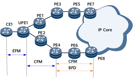
The MGR module helps associate CFM with other detection modules for fault notification. Currently, Ethernet in the First Mile (EFM), CFM, and Bidirectional Forwarding Detection (BFD) detection modules can be associated. Figure 2 shows the associations between CFM and other detection modules.
Table 1 describes the associations between CFM and other detection modules along the path CE1 -> UPE1 -> PE2 -> PE4 -> PE6 -> PE8.
Table 1 Associations between CFM and other detection modules Function Deployment
Issue
Solution
EFM is deployed to monitor the link between CE1 and UPE1, and CFM is deployed to monitor the link between PE4 and PE8.
When CFM detects a link fault, it does not notify CE1 of the fault. As a result, CE1 still forwards user-side traffic along the faulty link.
Associate EFM with CFM.If EFM detects a link fault, it instructs the MGR module to notify CFM of the fault.
If CFM detects a link fault, it instructs the MGR module to notify EFM of the fault.
CFM is deployed to monitor the links between UPE1 and PE4 and between PE4 and PE8.
Upon detecting a fault in the link between PE4 and PE8, CFM does not notify CE1 of the fault. As a result, CE1 continues to forward user-side traffic along the faulty link.
Upon detecting a fault in the link between UPE1 and PE4, CFM does not notify PE8 of the fault. As a result, PE8 continues to forward network-side traffic along the faulty link.
Associate CFM for the links between UPE1 and PE4 and with CFM for the links between PE4 and PE8. If CFM for either of the links detects a fault, it instructs the MGR module to notify the other CFM and sends an alarm to an NMS. The network administrator can analyze the alarm information and take measures to rectify the fault.
CFM is deployed to monitor the link between UPE1 and PE4.
A non-Ethernet link. BFD is deployed to monitor the link.
Upon detecting a link fault, CFM does not notify PE8 of the fault. As a result, PE8 continues to forward network-side traffic along the faulty link.
Upon detecting a link fault, BFD does not notify CE1 of the fault. As a result, CE1 continues to forward user-side traffic along the faulty link.
Associate CFM with BFD.If CFM detects a link fault, it instructs the MGR module to notify BFD of the fault.
If BFD detects a link fault, it instructs the MGR module to notify CFM of the fault.
Association between CFM and an application module
The MGR module helps to associate CFM with application modules to notify fault information between each other. Currently, the Virtual Router Redundancy Protocol (VRRP) application module can be associated.
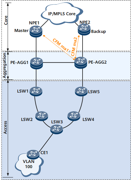
Figure 3 shows the association between CFM and VRRP in scenario 1.
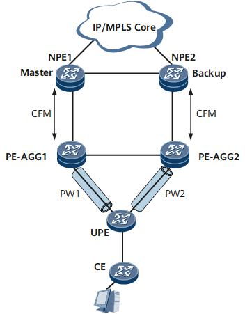
Figure 4 shows the association between VRRP and CFM in scenario 2.
Table 2 describes the associations between CFM and VRRP in scenario 1 and scenario 2.
Table 2 Associations between CFM and VRRP in scenario 1 and scenario 2 Function Deployment
Issue
Solution
VRRP is deployed on both NPE1 and NPE2.
CFM is deployed to monitor the links between NPE1 and PE-AGG1 and between NPE2 and PE-AGG2.
If the link between NPE1 (master) and PE-AGG1 fails and NPE2 does not receive VRRP Advertisement packets within a period of three times the interval at which VRRP Advertisement packets are sent, NPE2 preempts the Master state. As a result, two master devices coexist in a VRRP backup group, and duplicates of network-side traffic are transmitted.
Associate CFM with VRRP on NPE1 and NPE2. If CFM detects a fault in the link between PE-AGG2 and NPE1, CFM instructs the MGR module to notify VRRP of the fault. Then a master/backup VRRP switchover is performed. NPE1 changes its VRRP status to Initialize, and NPE2 changes its VRRP status from Backup to Master after a period of three times the interval at which VRRP Advertisement packets are sent. This process prevents a VRRP backup group from having two master devices.
VRRP is deployed on both NPE1 and NPE2.
CFM is deployed to monitor the links between NPE1 and PE-AGG1 and between NPE2 and PE-AGG2.
Pseudo wire (PW) redundancy is deployed to determine the primary/backup status of PWs.
If a fault occurs on the IP/Multiprotocol Label Switching (MPLS) core network, the fault triggers a master/backup VRRP switchover but does not trigger a primary/backup PW switchover. As a result, user-side traffic is lost.
Associate VRRP with CFM on NPE1 and NPE2.
When the master/backup status of NPE1 and NPE2 changes, VRRP instructs the MGR module to notify CFM of the status change. Then, CFM notifies PE-AGG1 and PE-AGG2 of the status change.
PE-AGG1 and PE-AGG2 determine the primary and backup PWs based on the status change.
Each PE-AGG notifies the UPE of the PW status change.
After the UPE receives the notification, it determines the primary/backup status of PWs.
When CFM detects a link fault, it triggers master/backup VRRP and primary/backup PW switchovers.
In addition, when CFM receives a fault notification, CFM can be associated with MAC/ARP clearing to ensure link switchovers.