Creating an MA
This section describes how to create a maintenance association (MA).
Context
Connectivity fault management (CFM) can detect direct or end-to-end link faults. As shown in Figure 1, CFM is deployed to monitor the link between the CE and PE3. PE3 is a Layer 2 device or a device that connects a Layer 2 network to a Layer 3 network.
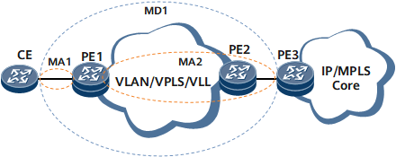
To deploy CFM to detect link faults, create an MD to determine a detected range, create MAs for the MD, and map the MAs to service instances. You can deploy multiple MAs in a single MD. For example, you can deploy MD1 between the CE and PE3 and create MA1, MA2, and MA3 in MD1 based on service types. Generally, each MA is mapped to a service instance and serves the service instance. The type of a service instance can be virtual local area network (VLAN), virtual private LAN service (VPLS), or virtual leased line (VLL).
Table 1 describes the rules for the association between MAs and service instances in different networking scenarios.
Networking Scenario |
Rule |
|---|---|
Direct link |
When an MA (for example, MA1 in the figure above) is deployed on directly connected devices and both interfaces of the direct link are Layer 2 interfaces, the MA does not need to be mapped to a service instance. |
End-to-end link |
When an MA (for example, MA2 in the figure above) is deployed on an end-to-end network, the MA needs to be mapped to a service instance. An MA can be mapped to a service instance directly or indirectly. As shown in Figure 1:
After an MA is mapped to a service instance, a maintenance point (MP) in the MA sends packets carrying the service instance's tag and receives packets from other MPs in the MA. This section describes how to directly map an MA to a service instance. For details about how to indirectly map an MA to a service instance, see Creating MEPs. |
Procedure
- Run system-view
The system view is displayed.
- Run cfm md md-name
The MD view is displayed.
- Run ma ma-name [ format { icc-based iccbased-ma-format-name | string ma-format-name } ]
An MA is created, and the MA view is displayed.
ITU-T Y.1731 defines ITU carrier code (ICC)-based continuity check messages (CCMs), which have similar formats to CCMs defined by IEEE 802.1ag. The meanings of some fields in an ICC-based CCM are different from those in a CCM defined by IEEE 802.1ag. To implement compatibility with ICC-based CCMs, specify the iccbased-ma-format-name parameter in this command.
- Configure the MA according to Table 2.
Table 2 MA configurations in different networking environments Networking Environment
Configuration Description
Direct link with Layer 2 interfaces configured at both ends
The MA does not need to be mapped to a service instance.
End-to-end link in VLAN scenarios
The MA is created on a Layer 2 device.
Run the map vlan vlan-id command to map the MA to a specified VLAN.
The MA is created on a device that connects a Layer 2 network to a Layer 3 network.
Specify a VLAN during MEP creation to map the MA to the VLAN. For details, see Creating MEPs.
End-to-end link in LDP VLL scenarios
Run the map mpls l2vc l2vc-id { tagged | raw } command on each Layer 2 device to associate the MA with a specified VLL.
End-to-end link in BGP VLL scenarios
Run the map l2vpn l2vpn-name ce ce-id ce-offset ce-offset-id command on each Layer 2 device to associate the MA with a specified VLL.
End-to-end link in VPLS scenarios
Run the map vsi vsi-name command on each Layer 2 device to map the MA to a specified virtual switching instance (VSI).
End-to-end link in CCC scenarios
Run the map ccc ccc-connection-name command on each Layer 2 device to associate the MA with a specified CCC.
End-to-end link in EVPN scenarios
Run the map evpn vpn-instance evpn-instance-name command on each Layer 2 device to associate the MA with a specified EVPN instance.
End-to-end link in BD scenarios
Run the map bridge-domain bd-id command on each Layer 2 device to associate the MA with a specified bridge domain.
- Run commit
The configuration is committed.