Example for Configuring Static VXLAN in an Active-Active Scenario (Layer 2 Communication)
In a scenario where a data center is interconnected with an enterprise site, a CE is dual-homed to a VXLAN network. Carriers can enhance VXLAN access reliability to improve the stability of user services so that rapid convergence can be implemented in the case of a fault.
Networking Requirements
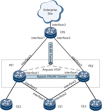
On the network shown in Figure 1, CE1 is dual-homed to PE1 and PE2 through an Eth-Trunk. PE1 and PE2 use the same virtual address as the source VTEP address of an NVE interface, namely, an anycast VTEP address. In this way, the CPE is aware of only one remote NVE interface and establishes a static VXLAN tunnel with the anycast VTEP address.
The packets from the CPE can reach CE1 through either PE1 or PE2. However, single-homed CEs may exist, such as CE2 and CE3. As a result, after reaching a PE, the packets from the CPE may need to be forwarded by the other PE to a single-homed CE. Therefore, a bypass VXLAN tunnel needs to be established between PE1 and PE2.

Interfaces 1 through 3 in this example represent GE 0/1/1, GE 0/1/2, and GE 0/1/3, respectively.
Device |
Interface |
IP Address |
|---|---|---|
PE1 |
GE 0/1/1 |
10.1.20.1/24 |
GE 0/1/2 |
- |
|
GE 0/1/3 |
10.1.1.1/24 |
|
Loopback 1 |
1.1.1.1/32 |
|
Loopback 2 |
3.3.3.3/32 |
|
PE2 |
GE 0/1/1 |
10.1.20.2/24 |
GE 0/1/2 |
- |
|
GE 0/1/3 |
10.1.2.1/24 |
|
Loopback 1 |
2.2.2.2/32 |
|
Loopback 2 |
3.3.3.3/32 |
|
CE1 |
GE 0/1/1 |
- |
GE 0/1/2 |
- |
|
CPE |
GE 0/1/1 |
10.1.1.2/24 |
GE 0/1/2 |
10.1.2.2/24 |
|
GE 0/1/3 |
- |
|
Loopback 1 |
4.4.4.4/32 |
Configuration Roadmap
The configuration roadmap is as follows:
- Configure an IGP on the PEs and CPE to implement network connectivity.
- On PE1 and PE2, Configure service access points and set the same ESI for the access links of CE1 so that CE1 is dual-homed to PE1 and PE2.
- Configure the same virtual anycast VTEP address on PE1 and PE2 as the source NVE interface address to establish a VXLAN tunnel with the CPE. Establish static VXLAN tunnels between the PEs and CPE so that the PEs and CEP can communicate.
- Establish an EVPN peer relationship between PE1 and PE2 to receive and send VXLAN EVPN routes.
- Configure EVPN instances in BD mode on PE1 and PE2 and bind the BD to the corresponding EVPN instances.
- Enable the inter-chassis VXLAN function on PE1 and PE2, configure different bypass addresses for PE1 and PE2, and establish a bypass VXLAN tunnel on PE1 and PE2 so that PE1 and PE2 can communicate.
- (Optional) Configure a UDP port on the PEs to prevent the receiving of replicated packets.
- Configure a BD on PE1 and PE2.
- On PE1 and PE2, enable routes to be sent to carry extended community attributes and the function of redirecting received routes carrying the extended VLAN community attribute.
- On PE1 and PE2, enable FRR for MAC routes between the local and remote ends. When a PE fails, the downstream traffic of the CPE can quickly switch to the other PE.
- (Optional) When PE1 and PE2 establish an EBGP peer relationship, set the function of not changing the next-hop addresses of routes. When PE1 and PE2 establish an IBGP peer relationship, this function is not required.
Data Preparation
To complete the configuration, you need the following data:
Interfaces and their IP addresses
Names of VPN and EVPN instances
VPN targets of the received and sent routes in VPN and EVPN instances
Procedure
- Assign an IP address to each interface on each node, and configure loopback interface addresses.
For detailed configurations, see Configuration Files.
- Configure an IGP. In this example, IS-IS is used.
For detailed configurations, see Configuration Files.
- Enable EVPN capabilities.
# Configure PE1.
<PE1> system-view
[~PE1] evpn
[*PE1-evpn] vlan-extend private enable
[*PE1-evpn] vlan-extend redirect enable
[*PE1-evpn] local-remote frr enable
[*PE1-evpn] bypass-vxlan enable
[*PE1-evpn] quit
[*PE1] commit
The configuration of PE2 is similar to the configuration of PE1. For configuration details, see Configuration Files in this section.
- Configure a BGP peer relationship between PE1 and PE2.
# Configure PE1.
[~PE1] bgp 100
[*PE1-bgp] peer 2.2.2.2 as-number 100
[*PE1-bgp] peer 2.2.2.2 connect-interface LoopBack 1
[*PE1-bgp] ipv4-family unicast
[*PE1-bgp-af-ipv4] undo synchronization
[*PE1-bgp-af-ipv4] peer 2.2.2.2 enable
[*PE1-bgp-af-ipv4] quit
[*PE1-bgp] l2vpn-family evpn
[*PE1-bgp-af-evpn] undo policy vpn-target
[*PE1-bgp-af-evpn] peer 2.2.2.2 enable
[*PE1-bgp-af-evpn] peer 2.2.2.2 advertise encap-type vxlan
[*PE1-bgp-af-evpn] quit
[*PE1-bgp] quit
[*PE1] commit
The configuration of PE2 is similar to the configuration of PE1. For configuration details, see Configuration Files in this section.
- Create a VXLAN tunnel.
- Configure CE1 to access the PEs.
Configure PE1.
[*PE1] e-trunk 1
[*PE1-e-trunk-1] priority 10
[*PE1-e-trunk-1] peer-address 2.2.2.2 source-address 1.1.1.1
[*PE1-e-trunk-1] quit
[*PE1] interface eth-trunk 1
[*PE1-Eth-Trunk1] mac-address 00e0-fc12-3456
[*PE1-Eth-Trunk1] mode lacp-static
[*PE1-Eth-Trunk1] e-trunk 1
[*PE1-Eth-Trunk1] e-trunk mode force-master
[*PE1-Eth-Trunk1] es track evpn-peer 2.2.2.2
[*PE1-Eth-Trunk1] esi 0000.0001.0001.0001.0001
[*PE1-Eth-Trunk1] quit
[*PE1] interface eth-trunk1.1 mode l2
[*PE1-Eth-Trunk1.1] encapsulation dot1q vid 1
[*PE1-Eth-Trunk1.1] rewrite pop single
[*PE1-Eth-Trunk1.1] bridge-domain 10
[*PE1-Eth-Trunk1.1] quit
[~PE1] commit
The configuration of PE2 is similar to the configuration of PE1. For configuration details, see Configuration Files in this section.
- Verify the configuration.
Run the display vxlan tunnel command on PE1 to view VXLAN tunnel information. The following example uses the command output on PE1.
[~PE1] display vxlan tunnel
Number of vxlan tunnel : 2
Tunnel ID   Source                Destination           State  Type     Uptime
-----------------------------------------------------------------------------------
4026531842  1.1.1.1               2.2.2.2               up     dynamic  00:43:14
4026531843  3.3.3.3               4.4.4.4               up     static   00:08:30
Configuration Files
PE1 configuration file
#
sysname PE1
#
evpn enhancement port 1345
#
evpn
 vlan-extend private enable
 vlan-extend redirect enable
 local-remote frr enable
 bypass-vxlan enable
#
evpn vpn-instance evpn1 bd-mode
 route-distinguisher 11:11
 vpn-target 1:1 export-extcommunity
 vpn-target 1:1 import-extcommunity
#
bridge-domain 10
 vxlan vni 10 split-horizon-mode
 evpn binding vpn-instance evpn1
#
e-trunk 1
 priority 10
 peer-address 2.2.2.2 source-address 1.1.1.1
#
isis 1
 network-entity 10.0000.0000.0001.00
 frr
#
interface Eth-Trunk1
 mac-address 00e0-fc12-3456
 mode lacp-static
 e-trunk 1
 e-trunk mode force-master
 es track evpn-peer 2.2.2.2
 esi 0000.0001.0001.0001.0001
#
interface Eth-Trunk1.1 mode l2
 encapsulation dot1q vid 1
 rewrite pop single
 bridge-domain 10
#
interface GigabitEthernet 0/1/1
 undo shutdown
 ip address 10.1.20.1 255.255.255.0
 isis enable 1
#
interface GigabitEthernet 0/1/2
 undo shutdown
 eth-trunk 1
#
interface GigabitEthernet 0/1/3
 undo shutdown
 ip address 10.1.1.1 255.255.255.0
 isis enable 1
#
interface LoopBack1
 ip address 1.1.1.1 255.255.255.255
 isis enable 1
#
interface LoopBack2
 ip address 3.3.3.3 255.255.255.255
 isis enable 1
#
interface Nve1
 source 3.3.3.3
 bypass source 1.1.1.1
 mac-address 00e0-fc12-7890
 vni 10 head-end peer-list protocol bgp
 vni 10 head-end peer-list 4.4.4.4
#
bgp 100
 peer 2.2.2.2 as-number 100
 peer 2.2.2.2 connect-interface LoopBack1
 #
 ipv4-family unicast
  undo synchronization
  peer 2.2.2.2 enable
 #
 l2vpn-family evpn
  undo policy vpn-target
  peer 2.2.2.2 enable
  peer 2.2.2.2 advertise encap-type vxlan
#
return
PE2 configuration file
#
sysname PE2
#
evpn enhancement port 1345
#
evpn
 vlan-extend redirect enable
 vlan-extend private enable
 local-remote frr enable
 bypass-vxlan enable
#
evpn vpn-instance evpn1 bd-mode
 route-distinguisher 22:22
 vpn-target 1:1 export-extcommunity
 vpn-target 1:1 import-extcommunity
#
bridge-domain 10
 vxlan vni 10 split-horizon-mode
 evpn binding vpn-instance evpn1
#
e-trunk 1
 priority 10
 peer-address 1.1.1.1 source-address 2.2.2.2
#
isis 1
 network-entity 10.0000.0000.0002.00
 frr
#
interface Eth-Trunk1
 mac-address 00e0-fc12-3456
 mode lacp-static
 e-trunk 1
 e-trunk mode force-master
 es track evpn-peer 1.1.1.1
 esi 0000.0001.0001.0001.0001
#
interface Eth-Trunk1.1 mode l2
 encapsulation dot1q vid 1
 rewrite pop single
 bridge-domain 10
#
interface GigabitEthernet 0/1/1
 undo shutdown
 ip address 10.1.20.2 255.255.255.0
 isis enable 1
#
interface GigabitEthernet 0/1/2
 undo shutdown
 eth-trunk 1
#
interface GigabitEthernet 0/1/3
 undo shutdown
 ip address 10.1.2.1 255.255.255.0
 isis enable 1
#
interface LoopBack1
 ip address 2.2.2.2 255.255.255.255
 isis enable 1
#
interface LoopBack2
 ip address 3.3.3.3 255.255.255.255
 isis enable 1
#
interface Nve1
 source 3.3.3.3
 bypass source 2.2.2.2
 mac-address 00e0-fc12-7890
 vni 10 head-end peer-list protocol bgp
 vni 10 head-end peer-list 4.4.4.4
#
bgp 100
 peer 1.1.1.1 as-number 100
 peer 1.1.1.1 connect-interface LoopBack1
 #
 ipv4-family unicast
  undo synchronization
  peer 1.1.1.1 enable
 #
 l2vpn-family evpn
  undo policy vpn-target
  peer 1.1.1.1 enable
  peer 1.1.1.1 advertise encap-type vxlan
#
return
CE1 configuration file
#
sysname CE
#
vlan batch 1 to 4094
#
interface Eth-Trunk1
 portswitch
 port link-type trunk
 port trunk allow-pass vlan 1
#
interface GigabitEthernet 0/1/1
 undo shutdown
 eth-trunk 1
#
interface GigabitEthernet 0/1/2
  undo shutdown
 eth-trunk 1
#
return
CPE configuration file
#
sysname CPE
#
bridge-domain 10
 vxlan vni 10 split-horizon-mode
#
isis 1
 network-entity 20.0000.0000.0001.00
 frr
#
interface GigabitEthernet0/1/1
 undo shutdown
 ip address 10.1.1.2 255.255.255.0
 isis enable 1
#
interface GigabitEthernet0/1/2
 undo shutdown
 ip address 10.1.2.2 255.255.255.0
 isis enable 1
#
interface GigabitEthernet0/1/3
 undo shutdown
 esi 0000.0000.0000.0000.0017
#
interface GigabitEthernet0/1/3.1 mode l2
 encapsulation dot1q vid 10
 rewrite pop single
 bridge-domain 10
#
interface LoopBack1
 ip address 4.4.4.4 255.255.255.255
 isis enable 1
#
interface Nve1
 source 4.4.4.4
 vni 10 head-end peer-list 3.3.3.3
#
return