Example for Configuring Interworking Between a VPLS in PW Redundancy Mode and an Anycast VXLAN in an EVPN Active-Active Scenario
This section provides an example for configuring interworking between a VPLS in PW redundancy mode and an anycast VXLAN in an EVPN active-active scenario.
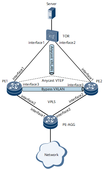
Networking Requirements
On the network shown in Figure 1, PE1 and PE2 are egress devices of the data center network. PE1 and PE2 work in active-active mode with a bypass VXLAN tunnel deployed between them. They use an anycast VTEP address to establish a VXLAN tunnel with the TOR. In this manner, PE1, PE2, and the TOR can communicate with each other. PE1 and PE2 communicate with the external network through the VPLS network, on which PW redundancy is configured. Specifically, the PE-AGG connects to PE1 and PE2 through primary and secondary PWs, respectively.

Interfaces 1 through 3 in this example represent GE 0/1/1, GE 0/1/2, and GE 0/1/3, respectively.
Device Name |
Interface |
IP Address and Mask |
|---|---|---|
PE1 |
GigabitEhernet 0/1/1 |
10.1.14.1/24 |
GigabitEhernet 0/1/2 |
10.1.13.1/24 |
|
GigabitEhernet 0/1/3 |
10.1.1.1/24 |
|
Loopback 1 |
1.1.1.1/32 |
|
Loopback 2 |
1.1.1.100/32 |
|
Loopback 3 |
1.1.1.20/32 |
|
PE2 |
GigabitEhernet 0/1/1 |
10.2.14.1/24 |
GigabitEhernet 0/1/2 |
10.2.13.1/24 |
|
GigabitEhernet 0/1/3 |
10.1.1.2/24 |
|
Loopback 1 |
2.2.2.2/32 |
|
Loopback 2 |
2.2.2.100/32 |
|
Loopback 3 |
1.1.1.20/32 |
|
PE-AGG |
GigabitEhernet 0/1/1 |
10.1.13.3/24 |
GigabitEhernet 0/1/2 |
10.2.13.3/24 |
|
Loopback 1 |
3.3.3.3/32 |
|
TOR |
GigabitEhernet 0/1/1 |
10.1.14.4/24 |
GigabitEhernet 0/1/2 |
10.2.14.4/24 |
|
Loopback 1 |
4.4.4.100/32 |
Configuration Roadmap
The configuration roadmap is as follows:
- Configure interface IP addresses, an IGP, and MPLS functions on each device.
- Configure BGP EVPN on PE1 and PE2.
- Configure a VXLAN tunnel between PE1 and PE2.
- Configure primary and secondary PWs on the PE-AGG.
- Configure PWs on PE1 and PE2 and set the PWs to AC mode.
Data Preparation
To complete the configuration, you need the following data:
Interfaces and their IP addresses
EVPN instance name
RD and RT of the EVPN instance
Procedure
- Configure interface IP addresses, an IGP, and MPLS functions on each device.
For configuration details, see Configuration Files in this section.
- Configure BGP EVPN on PE1 and PE2.
# Configure PE1.
[~PE1] evpn
[*PE1-evpn] bypass-vxlan enable
[*PE1-evpn] quit
[*PE1] bgp 100
[*PE1-bgp] peer 2.2.2.100 as-number 100
[*PE1-bgp] peer 2.2.2.100 connect-interface LoopBack 2
[*PE1-bgp] peer 4.4.4.100 as-number 100
[*PE1-bgp] peer 4.4.4.100 connect-interface LoopBack 2
[*PE1-bgp] l2vpn-family evpn
[*PE1-bgp-af-evpn] peer 2.2.2.100 enable
[*PE1-bgp-af-evpn] peer 2.2.2.100 advertise encap-type vxlan
[*PE1-bgp-af-evpn] peer 4.4.4.100 enable
[*PE1-bgp-af-evpn] peer 4.4.4.100 advertise encap-type vxlan
[*PE1-bgp-af-evpn] quit
[*PE1-bgp] quit
[*PE1] commit
Repeat this step for PE2. For configuration details, see Configuration Files in this section.
- Configure a VXLAN tunnel between PE1 and PE2.
- Configure primary and secondary PWs on the PE-AGG.
# Configure the PE-AGG.
[~PE-AGG] mpls l2vpn
[*PE-AGG-l2vpn] quit
[*PE-AGG] vsi vsi1 bd-mode
[*PE-AGG-vsi1] pwsignal ldp
[*PE-AGG-vsi1-ldp] vsi-id 1
[*PE-AGG-vsi1-ldp] peer 1.1.1.1
[*PE-AGG-vsi1-ldp] peer 2.2.2.2
[*PE-AGG-vsi1-ldp] protect-group 10
[*PE-AGG-vsi1-ldp-protect-group-10] protect-mode pw-redundancy master
[*PE-AGG-vsi1-ldp-protect-group-10] peer 1.1.1.1 preference 1
[*PE-AGG-vsi1-ldp-protect-group-10] peer 2.2.2.2 preference 2
[*PE-AGG-vsi1-ldp-protect-group-10] quit
[*PE-AGG-vsi1-ldp] quit
[*PE-AGG-vsi1] quit
[*PE-AGG] bridge-domain 10
[*PE-AGG-bd10] l2 binding vsi vsi1
[*PE-AGG-bd10] quit
[*PE-AGG] commit
- Configure PWs on PE1 and PE2 and set the PWs to AC mode.
# Configure PE1.
[~PE1] mpls l2vpn
[*PE1-l2vpn] quit
[*PE1] vsi vsi1 bd-mode
[*PE1-vsi1] pwsignal ldp
[*PE1-vsi1-ldp] vsi-id 1
[*PE1-vsi1-ldp] peer 3.3.3.3 ac-mode
[*PE1-vsi1-ldp] quit
[*PE1-vsi1] quit
[*PE1] bridge-domain 10
[*PE1-bd10] l2 binding vsi vsi1
[*PE1-bd10] quit
[*PE1] commit
Repeat this step for PE2. For configuration details, see Configuration Files in this section.
- Verify the configuration.
Run the display vxlan tunnel command on PE1 and check information about the VXLAN tunnels.
[~PE1] display vxlan tunnel
Number of vxlan tunnel : 2
Tunnel ID   Source                Destination           State  Type     Uptime
-----------------------------------------------------------------------------------
4026531842  1.1.1.100             2.2.2.100             up     dynamic  01:31:05
4026531843  1.1.1.20              4.4.4.100             up     dynamic  00:32:51
Run the display vsi command on PE1 and check the VSI status.
[~PE1] display vsi
Total VSI number is 1, 1 is up, 0 is down, 1 is LDP mode, 0 is BGP mode, 0 is BGPAD mode, 0 is mixed mode, 0 is unspecified mode
--------------------------------------------------------------------------
Vsi                             Mem    PW    Mac       Encap     Mtu   Vsi
Name                            Disc   Type  Learn     Type      Value State
--------------------------------------------------------------------------
vsi1                            --     ldp   qualify   vlan      1500  up
Run the display vsi name vsi1 protect-group 10 command on the PE-AGG and check information about the PW protection group in the VSI.
[~PE-AGG] display vsi name vsi1 protect-group 10
Protect-group: 10
-------------------------------------------------------------------------------
PeerIp:VcId                Pref   Active
-------------------------------------------------------------------------------
1.1.1.1:1                  1      Active
2.2.2.2:1                  2      Inactive
Configuration Files
PE1 configuration file
#
sysname PE1
#
evpn
 bypass-vxlan enable
#
evpn vpn-instance evpn1 bd-mode
 route-distinguisher 11:11
 vpn-target 1:1 export-extcommunity
 vpn-target 1:1 import-extcommunity
#
mpls lsr-id 1.1.1.1
#
mpls
#
mpls l2vpn
#
vsi vsi1 bd-mode
 pwsignal ldp
  vsi-id 1
  peer 3.3.3.3 ac-mode
#
bridge-domain 10
 vxlan vni 10 split-horizon-mode
 evpn binding vpn-instance evpn1
 l2 binding vsi vsi1
#
mpls ldp
#
isis 1
 network-entity 10.0000.0000.0001.00
#
interface GigabitEthernet0/1/1
 undo shutdown
 ip address 10.1.14.1 255.255.255.0
 isis enable 1
#
interface GigabitEthernet0/1/2
 undo shutdown
 ip address 10.1.13.1 255.255.255.0
 mpls
 mpls ldp
#
interface GigabitEthernet0/1/3
 undo shutdown
 ip address 10.1.1.1 255.255.255.0
 isis enable 1
#
interface LoopBack1
 ip address 1.1.1.1 255.255.255.255
#
interface LoopBack2
 ip address 1.1.1.100 255.255.255.255
 isis enable 1
#
interface LoopBack3
 ip address 1.1.1.20 255.255.255.255
 isis enable 1
#
interface Nve1
 source 1.1.1.20
 bypass source 1.1.1.100
 mac-address 00e0-fc12-3456
 vni 10 head-end peer-list protocol bgp
#
bgp 100
 peer 2.2.2.100 as-number 100
 peer 2.2.2.100 connect-interface LoopBack2
 peer 4.4.4.100 as-number 100
 peer 4.4.4.100 connect-interface LoopBack2
 #
 ipv4-family unicast
  undo synchronization
  peer 2.2.2.100 enable
  peer 4.4.4.100 enable
 #
 l2vpn-family evpn
  undo policy vpn-target
  peer 2.2.2.100 enable
  peer 2.2.2.100 advertise encap-type vxlan
  peer 4.4.4.100 enable
  peer 4.4.4.100 advertise encap-type vxlan
#
ospf 1
 area 0.0.0.0
  network 1.1.1.1 0.0.0.0
  network 10.1.13.0 0.0.0.255
#
return
PE2 configuration file
#
sysname PE2
#
evpn
 bypass-vxlan enable
#
evpn vpn-instance evpn1 bd-mode
 route-distinguisher 11:11
 vpn-target 1:1 export-extcommunity
 vpn-target 1:1 import-extcommunity
#
mpls lsr-id 2.2.2.2
#
mpls
#
mpls l2vpn
#
vsi vsi1 bd-mode
 pwsignal ldp
  vsi-id 1
  peer 3.3.3.3 ac-mode
#
bridge-domain 10
 vxlan vni 10 split-horizon-mode
 evpn binding vpn-instance evpn1
 l2 binding vsi vsi1
#
mpls ldp
#
isis 1
 network-entity 10.0000.0000.0002.00
#
interface GigabitEthernet0/1/1
 undo shutdown
 ip address 10.2.14.1 255.255.255.0
 isis enable 1
#
interface GigabitEthernet0/1/2
 undo shutdown
 ip address 10.2.13.1 255.255.255.0
 mpls
 mpls ldp
#
interface GigabitEthernet0/1/3
 undo shutdown
 ip address 10.1.1.2 255.255.255.0
 isis enable 1
#
interface LoopBack1
 ip address 2.2.2.2 255.255.255.255
#
interface LoopBack2
 ip address 2.2.2.100 255.255.255.255
 isis enable 1
#
interface LoopBack3
 ip address 1.1.1.20 255.255.255.255
 isis enable 1
#
interface Nve1
 source 1.1.1.20
 bypass source 2.2.2.100
 mac-address 00e0-fc12-3456
 vni 10 head-end peer-list protocol bgp
#
bgp 100
 peer 1.1.1.100 as-number 100
 peer 1.1.1.100 connect-interface LoopBack2
 peer 4.4.4.100 as-number 100
 peer 4.4.4.100 connect-interface LoopBack2
 #
 ipv4-family unicast
  undo synchronization
  network 1.1.1.20 255.255.255.255
  peer 1.1.1.100 enable
  peer 4.4.4.100 enable
 #
 l2vpn-family evpn
  undo policy vpn-target
  peer 1.1.1.100 enable
  peer 1.1.1.100 advertise encap-type vxlan
  peer 4.4.4.100 enable
  peer 4.4.4.100 advertise encap-type vxlan
#
ospf 1
 area 0.0.0.0
  network 2.2.2.2 0.0.0.0
  network 10.2.13.0 0.0.0.255
#
return
PE-AGG configuration file
#
sysname PE-AGG
#
mpls lsr-id 3.3.3.3
#
mpls
#
mpls l2vpn
#
vsi vsi1 bd-mode
 pwsignal ldp
  vsi-id 1
  peer 1.1.1.1
  peer 2.2.2.2
  protect-group 10
   protect-mode pw-redundancy master
   peer 1.1.1.1 preference 1
   peer 2.2.2.2 preference 2
#
bridge-domain 10
 l2 binding vsi vsi1
#
mpls ldp
#
interface GigabitEthernet0/1/1
 undo shutdown
 ip address 10.1.13.3 255.255.255.0
 mpls
 mpls ldp
#
interface GigabitEthernet0/1/2
 undo shutdown
 ip address 10.2.13.3 255.255.255.0
 mpls
 mpls ldp
#
interface LoopBack1
 ip address 3.3.3.3 255.255.255.255
#
ospf 1
 area 0.0.0.0
  network 3.3.3.3 0.0.0.0
  network 10.1.13.0 0.0.0.255
  network 10.2.13.0 0.0.0.255
#
return
TOR configuration file
See the configuration file of a DC device.