Example for Configuring DHCP Server Dual-Device Hot Backup
This section describes how to configure DHCP server dual-device hot backup on a VRRP group. After master/slave switching is implemented for the VRRP group, the new master device can properly process services with no need for re-synchronizing user session information.
Networking Requirements
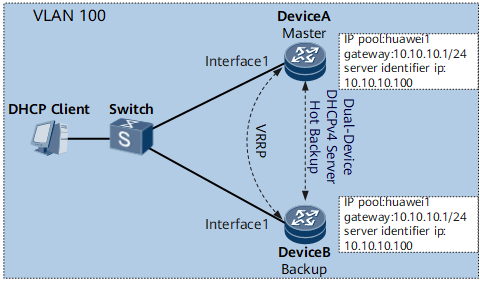
On the network shown in Figure 1, the DHCP client is connected to DeviceA and DeviceB over a switch. A VRRP group is configured between DeviceA and DeviceB to establish the master/backup relationship, with DeviceA as the master device and DeviceB as the backup device. Both DeviceA and DeviceB serve as a DHCP server to assign IP addresses to DHCP clients.
In normal cases, DeviceA implements new user access and online user renewal. When DeviceA or the link between DeviceA and the switch becomes faulty, a master/backup VRRP switchover is implemented and DeviceB takes over to become the master device. DeviceB can properly perform address assignment for new users and renewal requests for online users only when user session information has been synchronized from DeviceA to DeviceB.
To prevent abnormalities of new user access and online user renewal after a master/backup switchover due to a failure to synchronize user session information from DeviceA to DeviceB, deploy DHCP server dual-device hot backup on DeviceA and DeviceB.

Configuration Roadmap
The configuration roadmap is as follows:
Create a VLAN and configure the Layer 2 forwarding function.
Configure the address assignment function.
Establish a dual-device backup platform.
Enable remote backup for the DHCP server.
Data Preparation
To complete the configuration, you need the following data:
VLAN ID of DeviceA and DeviceB: 100
Gateway address of the address pool named pool1: 10.10.10.1/24; start IP address of the address segment: 10.10.10.1; end IP address of the address segment: 10.10.10.100
ID of the VRRP group established between DeviceA and DeviceB: 1; virtual IP address of the VRRP group: 10.10.10.100
Priority of the VRRP group on DeviceA: 200; preemption delay: 420s
Name of the RBS and RBP: service1; user backup ID: 1
DHCP server identifier of DeviceA and DeviceB: 10.10.10.100
Procedure
- Create a VLAN and configure the Layer 2 forwarding function.
# Configure DeviceA.
<HUAWEI> system-view
[~HUAWEI] sysname DeviceA
[*HUAWEI] commit
[~DeviceA] vlan 100
[*DeviceA-vlan100] commit
[~DeviceA-vlan100] quit
[~DeviceA] interface gigabitethernet 0/1/1
[~DeviceA-GigabitEthernet0/1/1] portswitch
[*DeviceA-GigabitEthernet0/1/1] undo shutdown
[*DeviceA-GigabitEthernet0/1/1] port link-type trunk
[*DeviceA-GigabitEthernet0/1/1] port trunk allow-pass vlan 100
[*DeviceA-GigabitEthernet0/1/1] commit
[~DeviceA-GigabitEthernet0/1/1] quit
# Configure DeviceB.
<HUAWEI> system-view
[~HUAWEI] sysname DeviceB
[*HUAWEI] commit
[~DeviceB] vlan 100
[*DeviceB-vlan100] commit
[~DeviceB-vlan100] quit
[~DeviceB] interface gigabitethernet 0/1/1
[~DeviceB-GigabitEthernet0/1/1] portswitch
[*DeviceB-GigabitEthernet0/1/1] undo shutdown
[*DeviceB-GigabitEthernet0/1/1] port link-type trunk
[*DeviceB-GigabitEthernet0/1/1] port trunk allow-pass vlan 100
[*DeviceB-GigabitEthernet0/1/1] commit
[~DeviceB-GigabitEthernet0/1/1] quit
- Configure the address assignment function.
# Configure DeviceA.
[~DeviceA] ip pool pool1 server
[*DeviceA-ip-pool-pool1] gateway 10.10.10.1 255.255.255.0
[*DeviceA-ip-pool-pool1] section 0 10.10.10.1 10.10.10.100
[*DeviceA-ip-pool-pool1] commit
[~DeviceA-ip-pool-pool1] quit
# Configure DeviceB.
[~DeviceB] ip pool pool1 server
[*DeviceB-ip-pool-pool1] gateway 10.10.10.1 255.255.255.0
[*DeviceB-ip-pool-pool1] section 0 10.10.10.1 10.10.10.100
[*DeviceB-ip-pool-pool1] commit
[~DeviceB-ip-pool-pool1] quit
- Establish a dual-device backup platform.
Configure basic functions of a VRRP group.
# Configure DeviceA.
[~DeviceA] interface Vlanif 100
[*DeviceA-Vlanif100] ip address 10.10.10.1 255.255.255.0
[*DeviceA-Vlanif100] vrrp vrid 1 virtual-ip 10.10.10.100
[*DeviceA-Vlanif100] vrrp vrid 1 priority 200
[*DeviceA-Vlanif100] vrrp vrid 1 preempt-mode timer delay 600
[*DeviceA-Vlanif100] vrrp recover-delay 20
[*DeviceA-Vlanif100] dhcp server enable
[*DeviceA-Vlanif100] commit
[~DeviceA-Vlanif100] quit
# Configure DeviceB.
[~DeviceB] interface Vlanif 100
[*DeviceB-Vlanif100] ip address 10.10.10.2 255.255.255.0
[*DeviceB-Vlanif100] vrrp vrid 1 virtual-ip 10.10.10.100
[*DeviceB-Vlanif100] dhcp server enable
[*DeviceB-Vlanif100] commit
[~DeviceB-Vlanif100] quit
Configure an RBS.
# Configure DeviceA.
[~DeviceA] remote-backup-service service1
[*DeviceA-rm-backup-srv-service1] peer 10.10.10.2 source 10.10.10.1 port 10000
[*DeviceA-rm-backup-srv-service1] commit
[~DeviceA-rm-backup-srv-service1] quit
# Configure DeviceB.[~DeviceB] remote-backup-service service1 [*DeviceB-rm-backup-srv-service1] peer 10.10.10.1 source 10.10.10.2 port 10000 [*DeviceB-rm-backup-srv-service1] commit [~DeviceB-rm-backup-srv-service1] quit
Configure an RBP.
# Configure DeviceA.
[~DeviceA] remote-backup-profile service1
[*DeviceA-rm-backup-prf-service1] peer-backup hot
[*DeviceA-rm-backup-prf-service1] vrrp-id 1 interface Vlanif 100
[*DeviceA-rm-backup-prf-service1] backup-id 1 remote-backup-service service1
[*DeviceA-rm-backup-prf-service1] commit
[~DeviceA-rm-backup-prf-service1] quit
# Configure DeviceB.[~DeviceB] remote-backup-profile service1 [*DeviceB-rm-backup-prf-service1] peer-backup hot [*DeviceB-rm-backup-prf-service1] vrrp-id 1 interface Vlanif 100 [*DeviceB-rm-backup-prf-service1] backup-id 1 remote-backup-service service1 [*DeviceB-rm-backup-prf-service1] commit [~DeviceB-rm-backup-prf-service1] quit
- Enable remote backup for the DHCP server.# Enable remote backup for the DHCP server in the RBP view of DeviceA and bind the RBP to the address pool named pool1.
[~DeviceA] remote-backup-profile service1
[~DeviceA-rm-backup-prf-service1] service-type dhcp-server
[*DeviceA-rm-backup-prf-service1] commit
[~DeviceA-rm-backup-prf-service1] quit
[~DeviceA] ip pool pool1
[~DeviceA-ip-pool-pool1] remote-backup-profile service1
[*DeviceA-ip-pool-pool1] server identifier ip 10.10.10.100
[*DeviceA-ip-pool-pool1] commit
[~DeviceA-ip-pool-pool1] quit
# Enable remote backup for the DHCP server in the RBP view of DeviceB and bind the RBP to the address pool named pool1.[~DeviceB] remote-backup-profile service1 [~DeviceB-rm-backup-prf-service1] service-type dhcp-server [*DeviceB-rm-backup-prf-service1] commit [~DeviceB-rm-backup-prf-service1] quit [~DeviceB] ip pool pool1 [~DeviceB-ip-pool-pool1] remote-backup-profile service1 [*DeviceB-ip-pool-pool1] server identifier ip 10.10.10.100 [*DeviceB-ip-pool-pool1] commit [~DeviceB-ip-pool-pool1] quit
- Verify the configuration.After completing the configurations, run the display remote-backup-profile command on DeviceA. The command output shows that the RBP service1 has been created and bound to the address pool pool1.
<DeviceA> display remote-backup-profile service1
 -----------------------------------------------
 Profile-Index        : 0x1000
 Profile-Name         : service1
 Service              : dhcp-server
 Remote-backup-service: service1
 Backup-ID            : 1
 track protocol       : VRRP
 VRRP-ID              : 1
 VRRP-Interface       : Vlanif100
 Access-Control       : --
 State                : Master
 Peer State           : --
 Interface            :
 Backup mode          : hot
 Slot-Number          : --
 Card-Number          : --
 Port-Number          : --
Run the display remote-backup-profile command on DeviceB. The command output shows that the RBP service1 has been created and bound to the address pool pool1.<DeviceB> display remote-backup-profile service1 ----------------------------------------------- Profile-Index : 0x1000 Profile-Name : service1 Service : dhcp-server Remote-backup-service: service1 Backup-ID : 1 track protocol : VRRP VRRP-ID : 1 VRRP-Interface : Vlanif100 Access-Control : -- State : Slave Peer State : -- Interface : Backup mode : hot Slot-Number : -- Card-Number : -- Port-Number : --Run the display remote-backup-service command on DeviceA. The command output shows that the RBS service1 has been created.<DeviceA> display remote-backup-service service1 ---------------------------------------------------------- Service-Index : 1 Service-Name : service1 TCP-State : Connected Peer-ip : 10.10.10.2 Source-ip : 10.10.10.1 TCP-Port : 10000 Track-BFD : -- SSL-Policy-Name : -- SSL-State : -- ----------------------------------------------------------Run the display remote-backup-service command on DeviceB. The command output shows that the RBS service1 has been created.<DeviceB> display remote-backup-service service1 ---------------------------------------------------------- Service-Index : 1 Service-Name : service1 TCP-State : Connected Peer-ip : 10.10.10.1 Source-ip : 10.10.10.2 TCP-Port : 10000 Track-BFD : -- SSL-Policy-Name : -- SSL-State : -- ----------------------------------------------------------
Configuration Files
DeviceA configuration file
#
sysname DeviceA
#
vlan batch 100
#
ip pool pool1 server
 gateway 10.10.10.1 255.255.255.0
 section 0 10.10.10.1 10.10.10.100
 server identifier ip 10.10.10.100
 remote-backup-profile service1
#
remote-backup-service service1
 peer 10.10.10.2 source 10.10.10.1 port 10000
#
remote-backup-profile service1
 service-type dhcp-server
 backup-id 1 remote-backup-service service1
 peer-backup hot
 vrrp-id 1 interface Vlanif100
#
interface Vlanif100
 ip address 10.10.10.1 255.255.255.0
 vrrp vrid 1 virtual-ip 10.10.10.100
 vrrp vrid 1 priority 200
 vrrp vrid 1 preempt-mode timer delay 600
 vrrp recover-delay 20
 dhcp server enable
#
interface GigabitEthernet0/1/1
 portswitch
 undo shutdown
 port link-type trunk
 port trunk allow-pass vlan 100
#
return
DeviceB configuration file
#
sysname DeviceB
#
vlan batch 100
#
ip pool pool1 server
 gateway 10.10.10.1 255.255.255.0
 section 0 10.10.10.1 10.10.10.100
 server identifier ip 10.10.10.100
 remote-backup-profile service1
#
remote-backup-service service1
 peer 10.10.10.1 source 10.10.10.2 port 10000
#
remote-backup-profile service1
 service-type dhcp-server
 backup-id 1 remote-backup-service service1
 peer-backup hot
 vrrp-id 1 interface Vlanif100
#
interface Vlanif100
 ip address 10.10.10.2 255.255.255.0
 vrrp vrid 1 virtual-ip 10.10.10.100
 dhcp server enable
#
interface GigabitEthernet0/1/1
 portswitch
 undo shutdown
 port link-type trunk
 port trunk allow-pass vlan 100
#
return