Example for Configuring Ethernet Sub-interfaces for Communication Between VLAN Users and Non-VLAN Users
This example describes how to configure communication between VLAN users and non-VLAN users.
Networking Requirements
Users in a community belong to different network segments. The network administrator in the community adds the users to different VLANs to simplify management. However, users in another community are not added to any VLAN. VLAN users must be able to communicate with non-VLAN users.
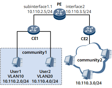
On the network shown in Figure 1, users in community 1 belong to different VLANs and network segments, and users in community 2 do not belong to any VLAN. It is required that users in VLAN 10 be able to communicate with users in community 2.

Precautions
- The IP address assigned to the sub-interface connected to VLAN users must be on the same network segment as IP addresses of VLAN users.
- The IP address assigned to the interface connected to non-VLAN users must be on the same network segment as IP addresses of non-VLAN users.
- The default gateway addresses of PCs in VLAN 10 must be the IP address of the sub-interface. Otherwise, VLAN and non-VLAN users cannot communicate with each other.
Configuration Roadmap
The configuration roadmap is as follows:
Create sub-interfaces on the PE and associate the sub-interfaces with VLANs so that the sub-interfaces can identify packets carrying VLAN tags.
Assign IP addresses to interfaces for communication at the network layer.
- Assign an IP address to the sub-interface.
- Assign an IP address to the interface connecting the PE to non-VLAN users.
Data Preparation
To complete the configuration, you need the following data:
VLAN ID associated with the PE sub-interface
IP address of the PE sub-interface
Procedure
- Create a sub-interface on the PE and associate the sub-interface with a VLAN.
<HUAWEI> system-view
[~HUAWEI] sysname PE
[*HUAWEI] commit
[~PE] interface gigabitethernet 0/1/1
[~PE-GigabitEthernet0/1/1] undo shutdown
[*PE] interface gigabitethernet 0/1/1.1
[*PE-GigabitEthernet0/1/1.1] vlan-type dot1q 10
- Configure IP addresses.
[*PE-GigabitEthernet0/1/1.1] ip address 10.110.2.5 24
[*PE-GigabitEthernet0/1/1.1] quit
[*PE] interface gigabitethernet 0/1/9
[*PE-GigabitEthernet0/1/9] undo shutdown
[*PE-GigabitEthernet0/1/9] ip address 10.110.3.5 24
[*PE-GigabitEthernet0/1/9] quit
[*PE] commit
- For the detailed configuration of the switch, see the related Configuration Guide.
- Verify the configuration.
On PCs in VLAN 10, configure the IP address 10.110.2.5/24 of GE 0/1/1.1 as the default gateway address.
On CE 2, configure the IP address 10.110.3.5 of GE 0/1/9 as the default gateway address.
After the configurations are complete, users in VLAN 10 and non-VLAN users can ping each other.