Example for Configuring an EVC Module to Transmit Layer 2 Multicast Services
This section provides an example for configuring an EVC module to transmit Layer 2 multicast services.
Networking Requirements
On a Layer 2 multicast network, a Layer 2 device sets up mappings between interfaces and multicast MAC addresses by analyzing Internet Group Management Protocol (IGMP) packets transmitted between Layer 3 devices and users. The mapping information helps implement on-demand multicast data forwarding at the data link layer. If Layer 2 multicast devices use multiple different access modes on a network, service management and configuration are complicated and difficult. To resolve this issue, configure an EVC module to transmit Layer 2 multicast services, implementing simplified network planning and management.
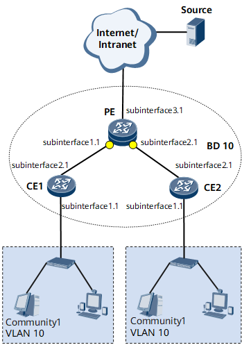
For example, on the network shown in Figure 1, a PE connects to a Layer 3 network, CE1 and CE2 connect to the PE. User terminals belong to VLAN 10.

After IGMP snooping is configured on the PE, multicast packets are sent only to access devices that have multicast receivers. If the topology is stable and hosts continuously require multicast data from the PE, configure the interface that connects the PE to the Layer 3 network as a static router interface.
Configuration Roadmap
The configuration roadmap is as follows:
Establish an EVC model.
Configure a BD to forward services.
Create EVC Layer 2 sub-interfaces, add them to the BD, and specify traffic encapsulation types and behaviors on downstream EVC Layer 2 sub-interfaces.
Configure Layer 2 multicast.
Configure basic IGMP snooping functions.
Specify GE 0/1/3.1 on the PE as a static router interface.
Data Preparation
To complete the configuration, you need the following data:
User VLAN IDs
Numbers of interfaces that connect CEs to users and connect CEs to PEs
BD ID, traffic encapsulation types, and traffic behaviors
Static router interface: GE 0/1/3.1
Procedure
- Establish an EVC model.
Configure a BD on the PE, CE1, and CE2.
# Configure the PE.
<HUAWEI> system-view
[~HUAWEI] sysname PE
[*HUAWEI] commit
[~PE] bridge-domain 10
[*PE-bd10] quit
# Configure CE1.
<HUAWEI> system-view
[~HUAWEI] sysname CE1
[*HUAWEI] commit
[~CE1] bridge-domain 10
[*CE1-bd10] quit
# Configure CE2.
<HUAWEI> system-view
[~HUAWEI] sysname CE2
[*HUAWEI] commit
[~CE2] bridge-domain 10
[*CE2-bd10] quit
Create EVC Layer 2 sub-interfaces, add them to the BD, and specify traffic encapsulation types and behaviors on downstream EVC Layer 2 sub-interfaces.
# Configure the PE.
[~PE] interface gigabitethernet 0/1/3
[*PE-GigabitEthernet0/1/3] undo shutdown
[*PE-GigabitEthernet0/1/3] quit
[*PE] interface gigabitethernet 0/1/3.1 mode l2
[*PE-GigabitEthernet0/1/3.1] encapsulation dot1q vid 10
[*PE-GigabitEthernet0/1/3.1] rewrite pop single
[*PE-GigabitEthernet0/1/3.1] bridge-domain 10
[*PE-GigabitEthernet0/1/3.1] commit
[~PE-GigabitEthernet0/1/3] quit
[*PE] interface gigabitethernet 0/1/1
[*PE-GigabitEthernet0/1/1] undo shutdown
[*PE-GigabitEthernet0/1/1] quit
[*PE] interface gigabitethernet 0/1/1.1 mode l2
[*PE-GigabitEthernet0/1/1.1] encapsulation dot1q vid 10
[*PE-GigabitEthernet0/1/1.1] rewrite pop single
[*PE-GigabitEthernet0/1/1.1] bridge-domain 10
[*PE-GigabitEthernet0/1/1.1] commit
[~PE-GigabitEthernet0/1/1] quit
[~PE] interface gigabitethernet 0/1/2
[*PE-GigabitEthernet0/1/2] undo shutdown
[*PE-GigabitEthernet0/1/2] quit
[*PE] interface gigabitethernet 0/1/2.1 mode l2
[*PE-GigabitEthernet0/1/2.1] encapsulation dot1q vid 10
[*PE-GigabitEthernet0/1/2.1] rewrite pop single
[*PE-GigabitEthernet0/1/2.1] bridge-domain 10
[*PE-GigabitEthernet0/1/2.1] commit
[~PE-GigabitEthernet0/1/2] quit
# Configure CE1.
[*CE1] interface gigabitethernet 0/1/1
[*CE1-GigabitEthernet0/1/1] undo shutdown
[*CE1-GigabitEthernet0/1/1] quit
[*CE1] interface gigabitethernet 0/1/1.1 mode l2
[*CE1-GigabitEthernet0/1/1.1] encapsulation dot1q vid 10
[*CE1-GigabitEthernet0/1/1.1] rewrite pop single
[*CE1-GigabitEthernet0/1/1.1] bridge-domain 10
[*CE1-GigabitEthernet0/1/1.1] commit
[~CE1-GigabitEthernet0/1/1] quit
[~CE1] interface gigabitethernet 0/1/2
[*CE1-GigabitEthernet0/1/2] undo shutdown
[*CE1-GigabitEthernet0/1/2] quit
[*CE1] interface gigabitethernet 0/1/2.1 mode l2
[*CE1-GigabitEthernet0/1/2.1] encapsulation dot1q vid 10
[*CE1-GigabitEthernet0/1/2.1] rewrite pop single
[*CE1-GigabitEthernet0/1/2.1] bridge-domain 10
[*CE1-GigabitEthernet0/1/2.1] commit
[~CE1-GigabitEthernet0/1/2] quit
# Configure CE2.
[*CE2] interface gigabitethernet 0/1/1
[*CE2-GigabitEthernet0/1/1] undo shutdown
[*CE2-GigabitEthernet0/1/1] quit
[*CE2] interface gigabitethernet 0/1/1.1 mode l2
[*CE2-GigabitEthernet0/1/1.1] encapsulation dot1q vid 10
[*CE2-GigabitEthernet0/1/1.1] rewrite pop single
[*CE2-GigabitEthernet0/1/1.1] bridge-domain 10
[*CE2-GigabitEthernet0/1/1.1] commit
[~CE2-GigabitEthernet0/1/1] quit
[~CE2] interface gigabitethernet 0/1/2
[*CE2-GigabitEthernet0/1/2] undo shutdown
[*CE2-GigabitEthernet0/1/2] quit
[*CE2] interface gigabitethernet 0/1/2.1 mode l2
[*CE2-GigabitEthernet0/1/2.1] encapsulation dot1q vid 10
[*CE2-GigabitEthernet0/1/2.1] rewrite pop single
[*CE2-GigabitEthernet0/1/2.1] bridge-domain 10
[*CE2-GigabitEthernet0/1/2.1] commit
[~CE2-GigabitEthernet0/1/2] quit
Verify the configuration.
After completing the configurations, run the display bridge-domain command to view BD information, including the BD to which an EVC Layer 2 sub-interface belongs and the BD status. The following example uses the command output on the PE.
[~PE] display bridge-domain
The total number of bridge-domains is : 1
--------------------------------------------------------------------------------
MAC_LRN: MAC learning;         STAT: Statistics;         SPLIT: Split-horizon;
BC: Broadcast;                 MC: Unknown multicast;    UC: Unknown unicast;
*down: Administratively down;  FWD: Forward;             DSD: Discard;
--------------------------------------------------------------------------------

BDID  State MAC-LRN STAT    BC  MC  UC  SPLIT   Description
--------------------------------------------------------------------------------
10    up    enable  disable FWD FWD FWD disable
- Configure Layer 2 multicast.
# Enable IGMP snooping globally on the PE.
[~PE] igmp-snooping enable# Enable IGMP snooping in BD 10 on the PE.
[*PE] bridge-domain 10
[*PE-bd10] igmp-snooping enable
[*PE-bd10] commit
[~PE-bd10] quit
# Specify GE 0/1/3.1 on the PE as a static router interface.
[~PE] interface gigabitethernet 0/1/3.1
[*PE-GigabitEthernet0/1/3.1] igmp-snooping static-router-port dot1q vid 10
[*PE-GigabitEthernet0/1/3.1] commit
- Verify the configuration.
# Run the display igmp-snooping bridge-domain configuration command on the PE to check whether IGMP snooping is enabled.
[*PE] display igmp-snooping bridge-domain configuration
 IGMP Snooping Configuration for bridge-domain 10
     igmp-snooping enable
# Run the display igmp-snooping router-port bridge-domain 10 command on the PE.
[*PE] display igmp-snooping router-port bridge-domain 10
 Port Name                         UpTime        Expires       Flags
 ---------------------------------------------------------------------
 Bridge-domain 10, 1 router-port(s)
 GE0/1/3.1(PE:10)                  00:01:02      --          STATIC
The command output shows that GE 0/1/3.1 is specified as a static router interface.
Configuration Files
PE configuration file
#
sysname PE
#
 igmp-snooping enable
#
bridge-domain 10
 igmp-snooping enable
#
interface GigabitEthernet0/1/3
 undo shutdown
#
interface GigabitEthernet0/1/3.1 mode l2
 encapsulation dot1q vid 10
 rewrite pop single
 bridge-domain 10
 igmp-snooping static-router-port dot1q vid 10
#
interface GigabitEthernet0/1/1
 undo shutdown
#
interface GigabitEthernet0/1/1.1 mode l2
 encapsulation dot1q vid 10
 rewrite pop single
 bridge-domain 10
#
interface GigabitEthernet0/1/2
 undo shutdown
#
interface GigabitEthernet0/1/2.1 mode l2
 encapsulation dot1q vid 10
 rewrite pop single
 bridge-domain 10
#
return
CE1 configuration file
#
sysname CE1
#
bridge-domain 10
#
interface GigabitEthernet0/1/1
 undo shutdown
#
interface GigabitEthernet0/1/1.1 mode l2
 encapsulation dot1q vid 10
 rewrite pop single
 bridge-domain 10
#
interface GigabitEthernet0/1/2
 undo shutdown
#
interface GigabitEthernet0/1/2.1 mode l2
 encapsulation dot1q vid 10
 rewrite pop single
 bridge-domain 10
#
return
CE2 configuration file
#
sysname CE2
#
bridge-domain 10
#
interface GigabitEthernet0/1/1
 undo shutdown
#
interface GigabitEthernet0/1/1.1 mode l2
 encapsulation dot1q vid 10
 rewrite pop single
 bridge-domain 10
#
interface GigabitEthernet0/1/2
 undo shutdown
#
interface GigabitEthernet0/1/2.1 mode l2
 encapsulation dot1q vid 10
 rewrite pop single
 bridge-domain 10
#
return