Configuring the EVC Model to Carry VPLS Services
This section describes how to use the EVC model to carry virtual private LAN service (VPLS) services to reduce enterprise costs.
Context
In the traditional service model supported by the NetEngine 8000 F, common sub-interfaces (VLAN type), dot1q VLAN tag termination sub-interfaces, or QinQ VLAN tag termination sub-interfaces are created on the user-side interfaces of PEs. These sub-interfaces are bound to different Virtual Switching Instances (VSIs) on the carrier network to isolate services in different departments of an enterprise. If the enterprise sets up another department, the enterprise must lease another VSI from the carrier to isolate the departments, which increases costs.
To allow the enterprise to dynamically adjust its departments and reduce costs, deploy the Ethernet Virtual Connection (EVC) model on the PEs to allow multiple Bridge Domains (BDs) to access the same VSI and also to be isolated from each other.
-
A VSI functions as a network-side pipe, and BDs function as service instances at the access layer. A VSI can carry service traffic from multiple BDs. The pseudowires (PWs) must work in tagged mode. The BDs must use VLAN IDs as service delimiters.
When a packet enters a PW from a BD, the ingress PE adds the BD ID to the packet as the outer tag (PW tag). When the packet leaves the PW, the egress PE searches for a VSI based on the VC label and searches for a BD based on the outer tag.
-
Each VSI provides access services for only one BD, and the BD exclusively consumes the VSI resources. The services in the VSI can be planned as needed. The PWs can work in either raw mode (with the VSI encapsulation type being Ethernet) or tagged mode (with the VSI encapsulation type being VLAN). The ingress PE adds a PW tag to packets that enter a PW only after the PW tag has been configured and the PW works in tagged mode. The egress PE does not verify the PW tag of packets that leave the PW. If the PW works in raw mode, the egress PE directly forwards the packets to the corresponding BD. If the PW works in tagged mode, the egress PE removes the outer tag before forwarding the packets to the corresponding BD.
Precautions
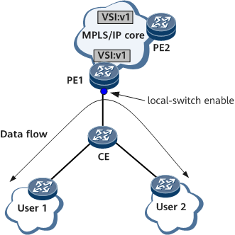
On the network shown in Figure 1, different user networks connect to PE1 through the same CE, and a BD is bound to a VSI for VPLS access. However, due to VPLS split horizon, the user-side interface on PE1 will not forward packets it receives, and therefore users in the same VSI cannot communicate. To allow users to communicate, run the local-switch enable command on the user-side Layer 2 sub-interface on PE1 to enable local switching for the Layer 2 sub-interface.
Pre-configuration Tasks
Before configuring the EVC model to carry VPLS services, create VSIs. VSI IDs are used to differentiate VSIs during PW signaling negotiation.
The VSIs for BDs must be configured using the vsi bd-mode command.

Ensure that MPLS L2VPN has been enabled on the device before you create VSIs.
Procedure
- Run system-view
The system view is displayed.
- Run bridge-domain bd-id
The BD view is displayed.
- Run l2 binding vsi vsi-name [ pw-tag pw-tag-value ]
The BD is bound to a VSI.
If the VSI pipe service mode is used, multiple BDs can access the same VSI. In this case, you must specify a PW tag so that the peer BD can receive packets from the BD with the same PW tag.
- (Optional) Run reserve-interface fast-switch enable
The reserve-interface fast switching function is enabled.
In a VPLS over EVC scenario where the public-network-and-private-network decoupling function is configured, to allow broadcast traffic to be rapidly switched to the slave interface board when the master interface board fails, perform this step.
- Run commit
The configuration is committed.
Follow-up Procedure
Run system-view
The system view is displayed.
Run vsi vsi-name
The VSI view is displayed.
-
The VSI is enabled to learn the AC interface Down event when all EVC Layer 2 sub-interfaces in a BD are Down.
Run commit
The configuration is committed.
Run system-view
The system view is displayed.
Run vsi vsi-name
The VSI view is displayed.
Run mac-withdraw bd-status down disable
The PE is configured not to send MAC Withdraw messages with the 0x404 TLV type to all its peers when a BD goes Down.
Run commit
The configuration is committed.
Run system-view
The system view is displayed.
- Run interface interface-type interface-number.subnum mode l2
The EVC Layer 2 sub-interface view is displayed.
Run interface-status-change [ up | down ] mac-withdraw enable
The PE is enabled to send a MAC Withdraw message to all its peers when the EVC Layer 2 sub-interface status changes.
Run quit
Return to the system view.
Run vsi vsi-name bd-mode
The BD VSI view is displayed.
-
MAC Withdraw is enabled.
Run mac-withdraw bd pw-tag enable
The PE is configured to send MAC Withdraw messages that carry the PW tag to its peers when a BD goes Down.
Run commit
The configuration is committed.
In EVC scenarios, when a BD accesses a VPLS network in VSI-exclusive service mode, PWs work in raw mode (with the VSI encapsulation type being VLAN). In this case, packets leaving PWs are directly forwarded without having the outer tag removed. To solve this problem, perform the following steps to configure the PWs to work in tagged mode, so that the outer tag is removed when the packets leave the PWs:
Run system-view
The system view is displayed.
- Run vsi vsi-name bd-mode
The BD VSI view is displayed.
Run pwsignal ldp
The VSI-LDP view is displayed.
Run vsi-id vsi-id
A VSI ID is configured.
Run peer peer-address
A peer is specified for the current VSI.
- Run peer peer-address pw pw-name
A PW is created for the VSI.
- Run encapsulation vlan pass
The BD VPLS tagged mode is enabled.
Run commit
The configuration is committed.