Example for Configuring Eth-Trunk Sub-interfaces to Access a BD EVPN (Dual-Homing Active-Active)
This section provides an example for configuring hybrid forwarding of Layer 2 and Layer 3 traffic in a scenario where a CE is dual-homed to PEs of a BD EVPN in active-active mode.
Networking Requirements
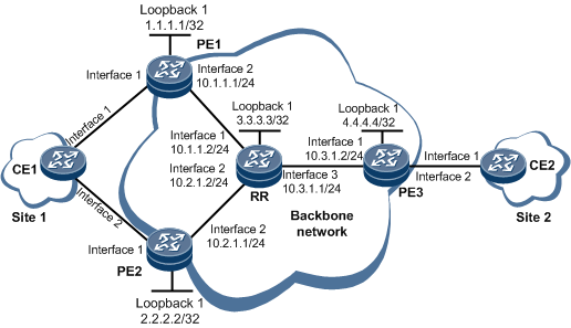
On the network shown in Figure 1, to allow sites to communicate over the backbone network, configure EVPN so that the sites can exchange EVPN routes to transmit Layer 2 traffic. If the sites belong to the same network segment, an EVPN instance is created on each PE to store MAC routes and perform Layer 2 forwarding based on MAC addresses. A route reflector (RR) is deployed to reflect EVPN routes.
To improve reliability in dual-homing active-active scenarios, configure the local and remote FRR function for MAC routes and BFD on PE1 and PE2.
Configuration Notes
When configuring an Eth-Trunk sub-interface to access a BD EVPN in dual-homing active-active mode, note the following:
- Currently, the dual-homing active-active mode can only be implemented by configuring an E-Trunk.
RTs in the export RT list of the EVPN instance on the local PE must be the same as RTs in the import RT list of the remote PE.
Using the local loopback interface address of each PE as an EVPN source address is recommended.
Configuration Roadmap
The configuration roadmap is as follows:
Configure an IGP on the backbone network to allow PEs and the RR to communicate.
Configure basic MPLS functions and enable MPLS LDP to establish LDP LSPs on the backbone network.
Configure a BD EVPN instance on each PE.
Configure an ESI and E-Trunk to implement the dual-homing active-active networking.
- Configure local-remote FRR for MAC routes.
- On PE1 and PE2, configure one BFD session for Eth-Trunk member interface detection and another BFD session for association with the access-side Eth-Trunk interface.
Establish BGP EVPN peer relationships.
Configure each CE to access the PEs through the Eth-Trunk interface.
- Configure IP addresses on the same network segment on CE1 and CE2. Perform a ping on the same network segment to instruct the local and remote PEs to learn the MAC address of the CE.
Data Preparation
To complete the configuration, you need the following data:
- EVPN instance name: evpna
EVPN instance evpna's RDs (100:1, 200:1, and 300:1) and RTs (1:1) on each PE
- Hold-down time (600000 ms) on the access-side interface of each PE (this configuration allows a PE to wait for the network-side EVPN service to recover before responding to the access-side interface up event)
- UDP port number for EVPN pruning status negotiation between active-active PEs: 1345
- Name of the BFD session for Eth-Trunk member interface detection: PEtoCE; names of BFD sessions for association with access-side Eth-Trunk interfaces: pe1tope2 and pe2tope1
Procedure
- Configure interface addresses on the RR and PEs according to Figure 1. For configuration details, see Configuration Files in this section.
- Configure an IGP on the backbone network, so that PEs can communicate with each other and with the RR. OSPF is used in this example.
# Configure PE1.
[~PE1] ospf 1
[*PE1-ospf-1] area 0
[*PE1-ospf-1-area-0.0.0.0] network 10.1.1.0 0.0.0.255
[*PE1-ospf-1-area-0.0.0.0] network 1.1.1.1 0.0.0.0
[*PE1-ospf-1-area-0.0.0.0] commit
[~PE1-ospf-1-area-0.0.0.0] quit
[~PE1-ospf-1] quit
# Configure PE2.
[~PE2] ospf 1
[*PE2-ospf-1] area 0
[*PE2-ospf-1-area-0.0.0.0] network 10.2.1.0 0.0.0.255
[*PE2-ospf-1-area-0.0.0.0] network 2.2.2.2 0.0.0.0
[*PE2-ospf-1-area-0.0.0.0] commit
[~PE2-ospf-1-area-0.0.0.0] quit
[~PE2-ospf-1] quit
# Configure PE3.
[~PE3] ospf 1
[*PE3-ospf-1] area 0
[*PE3-ospf-1-area-0.0.0.0] network 10.3.1.0 0.0.0.255
[*PE3-ospf-1-area-0.0.0.0] network 4.4.4.4 0.0.0.0
[*PE3-ospf-1-area-0.0.0.0] commit
[~PE3-ospf-1-area-0.0.0.0] quit
[~PE3-ospf-1] quit
# Configure the RR.
[~RR] ospf 1
[*RR-ospf-1] area 0
[*RR-ospf-1-area-0.0.0.0] network 10.1.1.0 0.0.0.255
[*RR-ospf-1-area-0.0.0.0] network 10.2.1.0 0.0.0.255
[*RR-ospf-1-area-0.0.0.0] network 10.3.1.0 0.0.0.255
[*RR-ospf-1-area-0.0.0.0] network 3.3.3.3 0.0.0.0
[*RR-ospf-1-area-0.0.0.0] commit
[~RR-ospf-1-area-0.0.0.0] quit
[~RR-ospf-1] quit
After the configurations are complete, PE1, PE2, and PE3 can establish OSPF neighbor relationships with the RR. Run the display ospf peer command. The command output shows that State is Full. Run the display ip routing-table command. The command output shows that the RR and PEs have learned the routes to Loopback1 of one another.
The command output on PE1 is used as an example.
[~PE1] display ospf peer
(M) Indicates MADJ neighbor


          OSPF Process 1 with Router ID 1.1.1.1
                Neighbors

 Area 0.0.0.0 interface 10.1.1.1 (GE0/1/8)'s neighbors
 Router ID: 3.3.3.3              Address: 10.1.1.2
   State: Full           Mode:Nbr is Master     Priority: 1
   DR: 10.1.1.1          BDR: 10.1.1.2          MTU: 0
   Dead timer due in  38  sec
   Retrans timer interval: 5
   Neighbor is up for 00h01m12s
   Neighbor Up Time : 2020-11-18 01:41:57
   Authentication Sequence: [ 0 ]
[~PE1] display ip routing-table
Route Flags: R - relay, D - download to fib, T - to vpn-instance, B - black hole route
------------------------------------------------------------------------------
Routing Table : _public_
         Destinations : 13       Routes : 13

Destination/Mask    Proto   Pre  Cost        Flags NextHop         Interface

        1.1.1.1/32  Direct  0    0             D   127.0.0.1       LoopBack1
        2.2.2.2/32  OSPF    10   2             D   10.1.1.2        GigabitEthernet0/1/8
        3.3.3.3/32  OSPF    10   1             D   10.1.1.2        GigabitEthernet0/1/8
        4.4.4.4/32  OSPF    10   2             D   10.1.1.2        GigabitEthernet0/1/8
      127.0.0.0/8   Direct  0    0             D   127.0.0.1       InLoopBack0
      127.0.0.1/32  Direct  0    0             D   127.0.0.1       InLoopBack0
127.255.255.255/32  Direct  0    0             D   127.0.0.1       InLoopBack0
      10.1.1.0/24   Direct  0    0             D   10.1.1.1        GigabitEthernet0/1/8
      10.1.1.1/32   Direct  0    0             D   127.0.0.1       GigabitEthernet0/1/8
    10.1.1.255/32   Direct  0    0             D   127.0.0.1       GigabitEthernet0/1/8
      10.2.1.0/24   OSPF    10   2             D   10.1.1.2        GigabitEthernet0/1/8
      10.3.1.0/24   OSPF    10   2             D   10.1.1.2        GigabitEthernet0/1/8
255.255.255.255/32  Direct  0    0             D   127.0.0.1       InLoopBack0
- Configure basic MPLS functions and enable MPLS LDP to establish LDP LSPs on the backbone network.
# Configure PE1.
[~PE1] mpls lsr-id 1.1.1.1
[*PE1] mpls
[*PE1-mpls] quit
[*PE1] mpls ldp
[*PE1-mpls-ldp] quit
[*PE1] interface gigabitethernet 0/1/8
[*PE1-GigabitEthernet0/1/8] mpls
[*PE1-GigabitEthernet0/1/8] mpls ldp
[*PE1-GigabitEthernet0/1/8] commit
[~PE1-GigabitEthernet0/1/8] quit
# Configure PE2.
[~PE2] mpls lsr-id 2.2.2.2
[*PE2] mpls
[*PE2-mpls] quit
[*PE2] mpls ldp
[*PE2-mpls-ldp] quit
[*PE2] interface gigabitethernet 0/1/8
[*PE2-GigabitEthernet0/1/8] mpls
[*PE2-GigabitEthernet0/1/8] mpls ldp
[*PE2-GigabitEthernet0/1/8] commit
[~PE2-GigabitEthernet0/1/8] quit
# Configure the RR.
[~RR] mpls lsr-id 3.3.3.3
[*RR] mpls
[*RR-mpls] quit
[*RR] mpls ldp
[*RR-mpls-ldp] quit
[*RR] interface gigabitethernet 0/1/0
[*RR-GigabitEthernet0/1/0] mpls
[*RR-GigabitEthernet0/1/0] mpls ldp
[*RR-GigabitEthernet0/1/0] quit
[*RR] interface gigabitethernet 0/1/8
[*RR-GigabitEthernet0/1/8] mpls
[*RR-GigabitEthernet0/1/8] mpls ldp
[*RR-GigabitEthernet0/1/8] quit
[*RR] interface gigabitethernet 0/1/16
[*RR-GigabitEthernet0/1/16] mpls
[*RR-GigabitEthernet0/1/16] mpls ldp
[*RR-GigabitEthernet0/1/16] commit
[~RR-GigabitEthernet0/1/16] quit
# Configure PE3.
[~PE3] mpls lsr-id 4.4.4.4
[*PE3] mpls
[*PE3-mpls] quit
[*PE3] mpls ldp
[*PE3-mpls-ldp] quit
[*PE3] interface gigabitethernet 0/1/0
[*PE3-GigabitEthernet0/1/0] mpls
[*PE3-GigabitEthernet0/1/0] mpls ldp
[*PE3-GigabitEthernet0/1/0] commit
[~PE3-GigabitEthernet0/1/0] quit
After the configurations are complete, LDP sessions can be established between the PEs (PE1, PE2, and PE3) and RR. Run the display mpls ldp session command. The command output shows that Status is Operational. Then, run the display mpls ldp lsp command. The command output shows that an LDP LSP has been successfully established on each device.
The command output on PE1 is used as an example.
[~PE1] display mpls ldp session
 LDP Session(s) in Public Network
 Codes: LAM(Label Advertisement Mode), SsnAge Unit(DDDD:HH:MM)
 An asterisk (*) before a session means the session is being deleted.
 --------------------------------------------------------------------------
 PeerID             Status      LAM  SsnRole  SsnAge       KASent/Rcv
 --------------------------------------------------------------------------
 3.3.3.3:0          Operational DU   Passive  0000:00:05   22/22
 --------------------------------------------------------------------------
 TOTAL: 1 Session(s) Found.
[~PE1] display mpls ldp lsp
 LDP LSP Information
 -------------------------------------------------------------------------------
 Flag after Out IF: (I) - RLFA Iterated LSP, (I*) - Normal and RLFA Iterated LSP
 -------------------------------------------------------------------------------
 DestAddress/Mask   In/OutLabel    UpstreamPeer    NextHop          OutInterface
 -------------------------------------------------------------------------------
 1.1.1.1/32         3/NULL         3.3.3.3         127.0.0.1        LoopBack1
*1.1.1.1/32         Liberal/32828                  DS/3.3.3.3
 2.2.2.2/32         NULL/32829     -               10.1.1.2         GE0/1/8
 2.2.2.2/32         32829/32829    3.3.3.3         10.1.1.2         GE0/1/8
 3.3.3.3/32         NULL/3         -               10.1.1.2         GE0/1/8
 3.3.3.3/32         32828/3        3.3.3.3         10.1.1.2         GE0/1/8
 4.4.4.4/32         NULL/32830     -               10.1.1.2         GE0/1/8
 4.4.4.4/32         32830/32830    3.3.3.3         10.1.1.2         GE0/1/8
 -------------------------------------------------------------------------------
 TOTAL: 7 Normal LSP(s) Found.
 TOTAL: 1 Liberal LSP(s) Found.
 TOTAL: 0 FRR LSP(s) Found.
 An asterisk (*) before an LSP means the LSP is not established
 An asterisk (*) before a Label means the USCB or DSCB is stale
 An asterisk (*) before an UpstreamPeer means the session is stale
 An asterisk (*) before a DS means the session is stale
 An asterisk (*) before a NextHop means the LSP is FRR LSP
- Configure an EVPN instance on each PE.
# Configure PE1.
[~PE1] evpn vpn-instance evpna bd-mode
[*PE1-evpn-instance-evpna] route-distinguisher 100:1
[*PE1-evpn-instance-evpna] vpn-target 1:1
[*PE1-evpn-instance-evpna] quit
[*PE1] bridge-domain 10
[*PE1-bd10] evpn binding vpn-instance evpna
[*PE1-bd10] quit
[*PE1] commit
# Configure PE2.
[~PE2] evpn vpn-instance evpna bd-mode
[*PE2-evpn-instance-evpna] route-distinguisher 200:1
[*PE2-evpn-instance-evpna] vpn-target 1:1
[*PE2-evpn-instance-evpna] quit
[*PE2] bridge-domain 10
[*PE2-bd10] evpn binding vpn-instance evpna
[*PE2-bd10] quit
[*PE2] commit
# Configure PE3.
[~PE3] evpn vpn-instance evpna bd-mode
[*PE3-evpn-instance-evpna] route-distinguisher 300:1
[*PE3-evpn-instance-evpna] vpn-target 1:1
[*PE3-evpn-instance-evpna] quit
[*PE3] bridge-domain 10
[*PE3-bd10] evpn binding vpn-instance evpna
[*PE3-bd10] quit
[*PE3] commit
- Configure a source address on each PE.
# Configure PE1.
[~PE1] evpn source-address 1.1.1.1
[*PE1] commit
# Configure PE2.
[~PE2] evpn source-address 2.2.2.2
[*PE2] commit
# Configure PE3.
[~PE3] evpn source-address 4.4.4.4
[*PE3] commit
- Configure an ESI and E-Trunk to implement the dual-homing active-active networking.
# Configure PE1.
[~PE1] lacp e-trunk system-id 00e0-fc00-0000
[*PE1] lacp e-trunk priority 1
[*PE1] e-trunk 1
[*PE1-e-trunk-1] peer-address 2.2.2.2  source-address 1.1.1.1
[*PE1-e-trunk-1] security-key cipher 00E0FC000000
[*PE1-e-trunk-1] quit
[*PE1] interface eth-trunk 10
[*PE1-Eth-Trunk10] mode lacp-static
[*PE1-Eth-Trunk10] e-trunk 1
[*PE1-Eth-Trunk10] e-trunk mode force-master
[*PE1-Eth-Trunk10] esi 0000.1111.2222.1111.1111
[*PE1-Eth-Trunk10] timer es-recovery 120
[*PE1-Eth-Trunk10] quit
[*PE1] interface eth-trunk 10.1 mode l2
[*PE1-Eth-Trunk10.1] encapsulation dot1q vid 2
[*PE1-Eth-Trunk10.1] rewrite pop single
[*PE1-Eth-Trunk10.1] bridge-domain 10
[*PE1-Eth-Trunk10.1] quit
[*PE1] interface gigabitethernet 0/1/0
[*PE1-GigabitEthernet0/1/0] eth-trunk 10
[*PE1-GigabitEthernet0/1/0] carrier up-hold-time 600000
[*PE1-GigabitEthernet0/1/0] quit
[*PE1] evpn enhancement port 1345
[*PE1] commit
# Configure PE2.
[~PE2] lacp e-trunk system-id 00e0-fc00-0000
[*PE2] lacp e-trunk priority 1
[*PE2] e-trunk 1
[*PE2-e-trunk-1] peer-address 1.1.1.1  source-address 2.2.2.2
[*PE2-e-trunk-1] security-key cipher 00E0FC000000
[*PE2-e-trunk-1] quit
[*PE2] interface eth-trunk 10
[*PE2-Eth-Trunk10] mode lacp-static
[*PE2-Eth-Trunk10] e-trunk 1
[*PE2-Eth-Trunk10] e-trunk mode force-master
[*PE2-Eth-Trunk10] esi 0000.1111.2222.1111.1111
[*PE2-Eth-Trunk10] timer es-recovery 120
[*PE2-Eth-Trunk10] quit
[*PE2] interface eth-trunk 10.1 mode l2
[*PE2-Eth-Trunk10.1] encapsulation dot1q vid 2
[*PE2-Eth-Trunk10.1] rewrite pop single
[*PE2-Eth-Trunk10.1] bridge-domain 10
[*PE2-Eth-Trunk10.1] quit
[*PE2] interface gigabitethernet 0/1/0
[*PE2-GigabitEthernet0/1/0] eth-trunk 10
[*PE2-GigabitEthernet0/1/0] carrier up-hold-time 600000
[*PE2-GigabitEthernet0/1/0] quit
[*PE2] evpn enhancement port 1345
[*PE2] commit
# Configure PE3.
[~PE3] interface eth-trunk 10
[*PE3-Eth-Trunk10] quit
[*PE3] interface eth-trunk 10.1 mode l2
[*PE3-Eth-Trunk10.1] encapsulation dot1q vid 2
[*PE3-Eth-Trunk10.1] rewrite pop single
[*PE3-Eth-Trunk10.1] bridge-domain 10
[*PE3-Eth-Trunk10.1] quit
[*PE3] interface gigabitethernet 0/1/8
[*PE3-GigabitEthernet0/1/8] eth-trunk 10
[*PE3-GigabitEthernet0/1/8] quit
[*PE3] commit
- Configure the local and remote FRR function for MAC routes on dual-homing PEs.
# Configure PE1.
[~PE1] evpn
[*PE1-evpn] vlan-extend private enable
[*PE1-evpn] vlan-extend redirect enable
[*PE1-evpn] local-remote frr enable
[*PE1-evpn] quit
[*PE1] commit
# Configure PE2.
[~PE2] evpn
[*PE2-evpn] vlan-extend private enable
[*PE2-evpn] vlan-extend redirect enable
[*PE2-evpn] local-remote frr enable
[*PE2-evpn] quit
[*PE2] commit
- On PE1 and PE2, configure a BFD session to monitor Eth-Trunk member interfaces; configure a BFD session and associate it with the access-side Eth-Trunk interface.
# Configure PE1.
[~PE1] bfd
[*PE1-bfd] quit
[*PE1] bfd PE1toCE bind peer-ip default-ip interface GigabitEthernet0/1/0
[*PE1-bfd-session-PE1toCE] discriminator local 1
[*PE1-bfd-session-PE1toCE] discriminator remote 2
[*PE1-bfd-session-PE1toCE] quit
[*PE1] bfd pe1tope2 bind peer-ip 2.2.2.2
[*PE1-bfd-session-pe1tope2] discriminator local 5
[*PE1-bfd-session-pe1tope2] discriminator remote 6
[*PE1-bfd-session-pe1tope2] quit
[*PE1] bfd pe2tope1 bind peer-ip 2.2.2.2 track-interface interface Eth-Trunk10
[*PE1-bfd-session-pe2tope1] discriminator local 7
[*PE1-bfd-session-pe2tope1] discriminator remote 8
[*PE1-bfd-session-pe2tope1] quit
[*PE1] interface eth-trunk 10
[*PE1-Eth-Trunk10] es track bfd pe1tope2
[*PE1-Eth-Trunk10] quit
[*PE1] commit
# Configure PE2.
[~PE2] bfd
[*PE2-bfd] quit
[*PE2] bfd PE2toCE bind peer-ip default-ip interface GigabitEthernet0/1/0
[*PE2-bfd-session-PE2toCE] discriminator local 3
[*PE2-bfd-session-PE2toCE] discriminator remote 4
[*PE2-bfd-session-PE2toCE] quit
[*PE2] bfd pe1tope2 bind peer-ip 1.1.1.1 track-interface interface Eth-Trunk10
[*PE2-bfd-session-pe1tope2] discriminator local 6
[*PE2-bfd-session-pe1tope2] discriminator remote 5
[*PE2-bfd-session-pe1tope2] quit
[*PE2] bfd pe2tope1 bind peer-ip 1.1.1.1
[*PE2-bfd-session-pe2tope1] discriminator local 8
[*PE2-bfd-session-pe2tope1] discriminator remote 7
[*PE2-bfd-session-pe2tope1] quit
[*PE2] interface eth-trunk 10
[*PE2-Eth-Trunk10] es track bfd pe2tope1
[*PE2-Eth-Trunk10] quit
[*PE2] commit
- Establish a BGP EVPN peer relationship.
# Configure PE1.
[~PE1] bgp 100
[*PE1-bgp] peer 3.3.3.3 as-number 100
[*PE1-bgp] peer 3.3.3.3 connect-interface loopback 1
[*PE1-bgp] l2vpn-family evpn
[*PE1-bgp-af-evpn] peer 3.3.3.3 enable
[*PE1-bgp-af-evpn] timer df-delay 0
[*PE1-bgp-af-evpn] quit
[*PE1-bgp] quit
[*PE1] commit
# Configure PE2.
[~PE2] bgp 100
[*PE2-bgp] peer 3.3.3.3 as-number 100
[*PE2-bgp] peer 3.3.3.3 connect-interface loopback 1
[*PE2-bgp] l2vpn-family evpn
[*PE2-bgp-af-evpn] peer 3.3.3.3 enable
[*PE2-bgp-af-evpn] timer df-delay 0
[*PE2-bgp-af-evpn] quit
[*PE2-bgp] quit
[*PE2] commit
# Configure PE3.
[~PE3] bgp 100
[*PE3-bgp] peer 3.3.3.3 as-number 100
[*PE3-bgp] peer 3.3.3.3 connect-interface loopback 1
[*PE3-bgp] l2vpn-family evpn
[*PE3-bgp-af-evpn] peer 3.3.3.3 enable
[*PE3-bgp-af-evpn] quit
[*PE3-bgp] quit
[*PE3] commit
# Configure the RR.
[~RR] bgp 100
[*RR-bgp] peer 1.1.1.1 as-number 100
[*RR-bgp] peer 1.1.1.1 connect-interface loopback 1
[*RR-bgp] peer 2.2.2.2 as-number 100
[*RR-bgp] peer 2.2.2.2 connect-interface loopback 1
[*RR-bgp] peer 4.4.4.4 as-number 100
[*RR-bgp] peer 4.4.4.4 connect-interface loopback 1
[*RR-bgp] l2vpn-family evpn
[*RR-bgp-af-evpn] undo policy vpn-target
[*RR-bgp-af-evpn] peer 1.1.1.1 enable
[*RR-bgp-af-evpn] peer 1.1.1.1 reflect-client
[*RR-bgp-af-evpn] peer 2.2.2.2 enable
[*RR-bgp-af-evpn] peer 2.2.2.2 reflect-client
[*RR-bgp-af-evpn] peer 4.4.4.4 enable
[*RR-bgp-af-evpn] peer 4.4.4.4 reflect-client
[*RR-bgp-af-evpn] quit
[*RR-bgp] quit
[*RR] commit
After completing the configurations, run the display bgp evpn peer command on the RR. The command output shows that BGP peer relationships have been established between the PEs and RR and are in the Established state.
[~RR] display bgp evpn peer BGP local router ID : 3.3.3.3 Local AS number : 100 Total number of peers : 3 Peers in established state : 3 Peer V AS MsgRcvd MsgSent OutQ Up/Down State PrefRcv 1.1.1.1 4 100 10 18 0 00:00:11 Established 6 2.2.2.2 4 100 10 20 0 00:00:12 Established 6 4.4.4.4 4 100 6 18 0 00:00:13 Established 2 - Configure the CE to access the PEs through the Eth-Trunk interface.
# Configure CE1.
[~CE1] vlan 2
[*CE1-vlan2] quit
[*CE1] interface Eth-Trunk10
[*CE1-Eth-Trunk10] portswitch
[*CE1-Eth-Trunk10] port link-type trunk
[*CE1-Eth-Trunk10] port trunk allow-pass vlan 2
[*CE1-Eth-Trunk10] mode lacp-static
[*CE1-Eth-Trunk10] quit
[*CE1] interface gigabitethernet0/1/0
[*CE1-GigabitEthernet0/1/0] eth-trunk 10
[*CE1-GigabitEthernet0/1/0] quit
[*CE1] interface gigabitethernet0/1/8
[*CE1-GigabitEthernet0/1/8] eth-trunk 10
[*CE1-GigabitEthernet0/1/8] quit
[*CE1] commit
# Configure CE2.
[~CE2] vlan 2
[*CE2-vlan2] quit
[*CE2] interface Eth-Trunk 10
[*CE2-Eth-Trunk10] portswitch
[*CE2-Eth-Trunk10] port link-type trunk
[*CE2-Eth-Trunk10] port trunk allow-pass vlan 2
[*CE2-Eth-Trunk10] quit
[*CE2] interface gigabitethernet0/1/0
[*CE2-GigabitEthernet0/1/0] eth-trunk 10
[*CE2-GigabitEthernet0/1/0] quit
[*CE2] commit
- Configure IP addresses on the same network segment on CE1 and CE2 and perform a ping operation on the same network segment.
# Configure CE1.
[~CE1] interface vlanif2
[~CE1-Vlanif2] ip address 192.168.1.11 24
[*CE1-Vlanif2] quit
[*CE1] bfd CEtoPE1 bind peer-ip default-ip interface GigabitEthernet0/1/0
[*CE1-bfd-session-CEtoPE1] discriminator local 2
[*CE1-bfd-session-CEtoPE1] discriminator remote 1
[*CE1-bfd-session-CEtoPE1] quit
[*CE1] bfd CEtoPE2 bind peer-ip default-ip interface GigabitEthernet0/1/8
[*CE1-bfd-session-CEtoPE2] discriminator local 4
[*CE1-bfd-session-CEtoPE2] discriminator remote 3
[*CE1-bfd-session-CEtoPE2] quit
[~CE1] commit
# Configure CE2.
[~CE2] interface vlanif2
[*CE2-Vlanif2] ip address 192.168.1.12 24
[*CE2-Vlanif2] quit
[~CE2] commit
# On CE1, ping an IP address on the same network segment as CE2. The following example uses the command output on CE1.
[~CE1] ping 192.168.1.12 PING 192.168.1.12: 56 data bytes, press CTRL_C to break Reply from 192.168.1.12: bytes=56 Sequence=1 ttl=255 time=13 ms Reply from 192.168.1.12: bytes=56 Sequence=2 ttl=255 time=4 ms Reply from 192.168.1.12: bytes=56 Sequence=3 ttl=255 time=3 ms Reply from 192.168.1.12: bytes=56 Sequence=4 ttl=255 time=4 ms Reply from 192.168.1.12: bytes=56 Sequence=5 ttl=255 time=4 ms --- 192.168.1.12 ping statistics --- 5 packet(s) transmitted 5 packet(s) received 0.00% packet loss round-trip min/avg/max = 3/5/13 ms - Verify the configuration.
Run the display bgp evpn all routing-table mac-route command on PE3. The command output shows the MAC route sent by the remote PE and the MAC route destined for CE1. In the active-active scenario, the next hops of the MAC routes on CE1 are PE1 and PE2, implementing load balancing.

After PE1 and PE2 learn MAC address information from CE1, you can run the display bgp evpn all routing-table mac-route command on PE3 to view the following information. If only one PE learns MAC address information and synchronizes the information to the other PE through EVPN, you need to run the display mac-address command on PE3 to view the load balancing status of MAC routes.
[~PE3] display bgp evpn all routing-table mac-route
 Local AS number : 100

 BGP Local router ID is 10.3.1.2
 Status codes: * - valid, > - best, d - damped, x - best external, a - add path,
               h - history,  i - internal, s - suppressed, S - Stale
               Origin : i - IGP, e - EGP, ? - incomplete

 EVPN address family:
 Number of Mac Routes: 3
 Route Distinguisher: 100:1
       Network(EthTagId/MacAddrLen/MacAddr/IpAddrLen/IpAddr)  NextHop
 *>i   0:48:00e0-fc12-5678:32:0.0.0.0                         1.1.1.1
 Route Distinguisher: 200:1
       Network(EthTagId/MacAddrLen/MacAddr/IpAddrLen/IpAddr)  NextHop
 *>i   0:48:00e0-fc12-5678:32:0.0.0.0                         2.2.2.2
 Route Distinguisher: 300:1
       Network(EthTagId/MacAddrLen/MacAddr/IpAddrLen/IpAddr)  NextHop
 *>    0:48:00e0-fc12-3333:32:0:0.0.0.0                       0.0.0.0


 EVPN-Instance evpna:
 Number of Mac Routes: 2
       Network(EthTagId/MacAddrLen/MacAddr/IpAddrLen/IpAddr)  NextHop
 *>i   0:48:00e0-fc12-5678:32:0.0.0.0                         1.1.1.1
 * i                                                          2.2.2.2
 *>    0:48:00e0-fc12-3333:32:0:0.0.0.0                       0.0.0.0
Configuration Files
PE1 configuration file
#
sysname PE1
#
lacp e-trunk system-id 00e0-fc00-0000
lacp e-trunk priority 1
#
evpn enhancement port 1345
#
evpn
 vlan-extend private enable
 vlan-extend redirect enable
 local-remote frr enable
 #
 mac-duplication
#
evpn vpn-instance evpna bd-mode
 route-distinguisher 100:1
 vpn-target 1:1 export-extcommunity
 vpn-target 1:1 import-extcommunity
#
bfd
#
mpls lsr-id 1.1.1.1
#
mpls
#
bridge-domain 10
 evpn binding vpn-instance evpna
#
mpls ldp
 #
 ipv4-family
#
e-trunk 1
 peer-address 2.2.2.2 source-address 1.1.1.1
 security-key cipher %^%#VQE;E!Dl&Rr]if$F>}w9uk5C>y-4|MS$unQ!#Mb#%^%#
 authentication-mode enhanced-hmac-sha256
#
interface Eth-Trunk10
 mode lacp-static
 e-trunk 1
 e-trunk mode force-master
 es track bfd pe1tope2
 esi 0000.1111.2222.1111.1111
 timer es-recovery 120
#
interface Eth-Trunk10.1 mode l2
 encapsulation dot1q vid 2
 rewrite pop single
 bridge-domain 10
#
interface GigabitEthernet0/1/0
 undo shutdown
 carrier up-hold-time 600000
 eth-trunk 10
#
interface GigabitEthernet0/1/8
 undo shutdown
 ip address 10.1.1.1 255.255.255.0
 mpls
 mpls ldp
#
interface LoopBack1
 ip address 1.1.1.1 255.255.255.255
#
bfd pe1tope2 bind peer-ip 2.2.2.2
 discriminator local 5
 discriminator remote 6
#
bfd pe2tope1 bind peer-ip 2.2.2.2 track-interface interface Eth-Trunk10
 discriminator local 7
 discriminator remote 8
#
bfd PE1toCE bind peer-ip default-ip interface GigabitEthernet0/1/0
 discriminator local 1
 discriminator remote 2
#
bgp 100
 peer 3.3.3.3 as-number 100
 peer 3.3.3.3 connect-interface LoopBack1
 #
 ipv4-family unicast
  undo synchronization
  peer 3.3.3.3 enable
 #
 l2vpn-family evpn
  policy vpn-target
  timer df-delay 0
  peer 3.3.3.3 enable
#
ospf 1
 area 0.0.0.0
  network 1.1.1.1 0.0.0.0
  network 10.1.1.0 0.0.0.255
#
evpn source-address 1.1.1.1
#
return
PE2 configuration file
#
sysname PE2
#
lacp e-trunk system-id 00e0-fc00-0000
lacp e-trunk priority 1
#
evpn enhancement port 1345
#
evpn
 vlan-extend private enable
 vlan-extend redirect enable
 local-remote frr enable
 #
 mac-duplication
#
evpn vpn-instance evpna bd-mode
 route-distinguisher 200:1
 vpn-target 1:1 export-extcommunity
 vpn-target 1:1 import-extcommunity
#
bfd
#
mpls lsr-id 2.2.2.2
#
mpls
#
bridge-domain 10
 evpn binding vpn-instance evpna
#
mpls ldp
 #
 ipv4-family
#
e-trunk 1
 peer-address 1.1.1.1 source-address 2.2.2.2
 security-key cipher %^%#VQE;E!Dl&Rr]if$F>}w9uk5C>y-4|MS$unQ!#Mb#%^%#
 authentication-mode enhanced-hmac-sha256
#
interface Eth-Trunk10
 mode lacp-static
 e-trunk 1
 e-trunk mode force-master
 es track bfd pe2tope1
 esi 0000.1111.2222.1111.1111
 timer es-recovery 120
#
interface Eth-Trunk10.1 mode l2
 encapsulation dot1q vid 2
 rewrite pop single
 bridge-domain 10
#
interface GigabitEthernet0/1/0
 undo shutdown
 carrier up-hold-time 600000
 eth-trunk 10
#
interface GigabitEthernet0/1/8
 undo shutdown
 ip address 10.2.1.1 255.255.255.0
 mpls
 mpls ldp
#
interface LoopBack1
 ip address 2.2.2.2 255.255.255.255
#
bfd pe1tope2 bind peer-ip 1.1.1.1 track-interface interface Eth-Trunk10
 discriminator local 6
 discriminator remote 5
#
bfd pe2tope1 bind peer-ip 1.1.1.1
 discriminator local 8
 discriminator remote 7
#
bfd PE2toCE bind peer-ip default-ip interface GigabitEthernet0/1/0
 discriminator local 3
 discriminator remote 4
#
bgp 100
 peer 3.3.3.3 as-number 100
 peer 3.3.3.3 connect-interface LoopBack1
 #
 ipv4-family unicast
  undo synchronization
  peer 3.3.3.3 enable
 #
 l2vpn-family evpn
  policy vpn-target
  timer df-delay 0
  peer 3.3.3.3 enable
#
ospf 1
 area 0.0.0.0
  network 2.2.2.2 0.0.0.0
  network 10.2.1.0 0.0.0.255
#
evpn source-address 2.2.2.2
#
return
PE3 configuration file
#
sysname PE3
#
evpn vpn-instance evpna bd-mode
 route-distinguisher 300:1
 vpn-target 1:1 export-extcommunity
 vpn-target 1:1 import-extcommunity
#
mpls lsr-id 4.4.4.4
#
mpls
#
bridge-domain 10
 evpn binding vpn-instance evpna
#
mpls ldp
 #
 ipv4-family
#
interface Eth-Trunk10
#
interface Eth-Trunk10.1 mode l2
 encapsulation dot1q vid 2
 rewrite pop single
 bridge-domain 10
#
interface GigabitEthernet0/1/0
 undo shutdown
 ip address 10.3.1.2 255.255.255.0
 mpls
 mpls ldp
#
interface GigabitEthernet0/1/8
 undo shutdown
 eth-trunk 10
#
interface LoopBack1
 ip address 4.4.4.4 255.255.255.255
#
bgp 100
 peer 3.3.3.3 as-number 100
 peer 3.3.3.3 connect-interface LoopBack1
 #
 ipv4-family unicast
  undo synchronization
  peer 3.3.3.3 enable
 #
 l2vpn-family evpn
  policy vpn-target
  peer 3.3.3.3 enable
#
ospf 1
 area 0.0.0.0
  network 4.4.4.4 0.0.0.0
  network 10.3.1.0 0.0.0.255
#
evpn source-address 4.4.4.4
#
return
RR configuration file
#
sysname RR
#
mpls lsr-id 3.3.3.3
#
mpls
#
mpls ldp
 #
 ipv4-family
#
interface GigabitEthernet0/1/0
 undo shutdown
 ip address 10.1.1.2 255.255.255.0
 mpls
 mpls ldp
#
interface GigabitEthernet0/1/8
 undo shutdown
 ip address 10.2.1.2 255.255.255.0
 mpls
 mpls ldp
#
interface GigabitEthernet0/1/16
 undo shutdown
 ip address 10.3.1.1 255.255.255.0
 mpls
 mpls ldp
#
interface LoopBack1
 ip address 3.3.3.3 255.255.255.255
#
bgp 100
 peer 1.1.1.1 as-number 100
 peer 1.1.1.1 connect-interface LoopBack1
 peer 2.2.2.2 as-number 100
 peer 2.2.2.2 connect-interface LoopBack1
 peer 4.4.4.4 as-number 100
 peer 4.4.4.4 connect-interface LoopBack1
 #
 ipv4-family unicast
  undo synchronization
  peer 1.1.1.1 enable
  peer 2.2.2.2 enable
  peer 4.4.4.4 enable
 #
 l2vpn-family evpn
  undo policy vpn-target
  peer 1.1.1.1 enable
  peer 1.1.1.1 reflect-client
  peer 2.2.2.2 enable
  peer 2.2.2.2 reflect-client
  peer 4.4.4.4 enable
  peer 4.4.4.4 reflect-client
#
ospf 1
 area 0.0.0.0
  network 3.3.3.3 0.0.0.0
  network 10.1.1.0 0.0.0.255
  network 10.2.1.0 0.0.0.255
  network 10.3.1.0 0.0.0.255
#
return
CE1 configuration file
#
sysname CE1
#
vlan batch 2
#
vlan 2
#
bfd
#
interface Vlanif2
 ip address 192.168.1.11 255.255.255.0
#
interface Eth-Trunk10
 portswitch
 port link-type trunk
 port trunk allow-pass vlan 2
 mode lacp-static
#
interface GigabitEthernet0/1/0
 undo shutdown
 eth-trunk 10
#
interface GigabitEthernet0/1/8
 undo shutdown
 eth-trunk 10
#
bfd CEtoPE1 bind peer-ip default-ip interface GigabitEthernet0/1/0
 discriminator local 2
 discriminator remote 1
#
bfd CEtoPE2 bind peer-ip default-ip interface GigabitEthernet0/1/8
 discriminator local 4
 discriminator remote 3
#
return
CE2 configuration file
#
sysname CE2
#
vlan batch 2
#
vlan 2
#
interface Vlanif2
 ip address 192.168.1.12 255.255.255.0
#
interface Eth-Trunk10
 portswitch
 port link-type trunk
 port trunk allow-pass vlan 2
#
interface GigabitEthernet0/1/0
 undo shutdown
 eth-trunk 10
#
return