Example for Configuring an EVPN L3VPN H-VPN
This section provides an example for configuring an EVPN L3VPN H-VPN to implement network interworking.
Networking Requirements
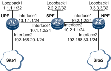
At present, the IP bearer network uses L2VPN and L3VPN (HVPN) to carry Layer 2 and Layer 3 services, respectively. The protocols are complex. EVPN can carry both Layer 2 and Layer 3 services. To simplify service bearer protocols, many IP bearer networks will evolve to EVPN. Specifically, L3VPN HVPN, which carries Layer 3 services, needs to evolve to EVPN L3VPN HVPN. On the network shown in Figure 1, the UPE and SPE are connected at the access layer, and the SPE and NPE are connected at the aggregation layer. Before an EVPN L3VPN H-VPN is deployed to implement E2E interworking, separate IGPs must be deployed at the access and aggregation layers to implement interworking at the different layers. On an EVPN L3VPN H-VPN, UPEs function as RR clients to receive the specific routes reflected by SPEs functioning as RRs. This mechanism facilitates route management and traffic forwarding control.

Configuration Roadmap
The configuration roadmap is as follows:
Deploy IGPs on the UPE, SPE, and NPE. In this example, OSPF runs between the UPE and SPE, and IS-IS runs between the SPE and NPE.
Configure MPLS LDP on the UPE, SPE, and NPE.
Create a VPN instance on each of the UPE and NPE.
Bind the VPN instances to the AC interfaces on the UPE and NPE.
Configure BGP-EVPN peer relationships between the UPE and SPE, and between the SPE and NPE.
On the SPE, specify the UPE as the BGP-EVPN RR client, and configure the SPE to use its own IP address as the next hop of BGP EVPN routes being advertised to the peer.
Data Preparation
To complete the configuration, you need the following data:
MPLS LSR IDs of the UPE (1.1.1.1), SPE (2.2.2.2), and NPE (3.3.3.3)
VPN instance name (vpn1) and RD (100:1)
VPN targets 2:2 for EVPN
Procedure
- Assign an IP address to each device interface, including the loopback interfaces.
For configuration details, see Configuration Files in this section.
- Deploy IGPs on the UPE, SPE, and NPE. In this example, OSPF runs between the UPE and SPE, and IS-IS runs between the SPE and NPE.
For configuration details, see Configuration Files in this section.
- Configure MPLS LDP on the UPE, SPE, and NPE.
For configuration details, see Configuration Files in this section.
- Create a VPN instance on each of the UPE and NPE.
# Configure the UPE.
[~UPE] ip vpn-instance vpn1
[*UPE-vpn-instance-vpn1] ipv4-family
[*UPE-vpn-instance-vpn1-af-ipv4] route-distinguisher 100:1
[*UPE-vpn-instance-vpn1-af-ipv4] vpn-target 2:2 both evpn
[*UPE-vpn-instance-vpn1-af-ipv4] evpn mpls routing-enable
[*UPE-vpn-instance-vpn1-af-ipv4] quit
[*UPE-vpn-instance-vpn1] quit
[*UPE] commit
# Configure the NPE.
[~NPE] ip vpn-instance vpn1
[*NPE-vpn-instance-vpn1] ipv4-family
[*NPE-vpn-instance-vpn1-af-ipv4] route-distinguisher 100:1
[*NPE-vpn-instance-vpn1-af-ipv4] vpn-target 2:2 both evpn
[*NPE-vpn-instance-vpn1-af-ipv4] evpn mpls routing-enable
[*NPE-vpn-instance-vpn1-af-ipv4] quit
[*NPE-vpn-instance-vpn1] quit
[*NPE] commit
- Bind the VPN instances to the AC interfaces on the UPE and NPE.
# Configure the UPE.
[~UPE] interface GigabitEthernet 0/1/8
[*UPE-GigabitEthernet0/1/8] ip binding vpn-instance vpn1
[*UPE-GigabitEthernet0/1/8] ip address 192.168.20.1 255.255.255.0
[*UPE-GigabitEthernet0/1/8] quit
[*UPE] commit
# Configure the NPE.
[~NPE] interface GigabitEthernet 0/1/8
[*NPE-GigabitEthernet0/1/8] ip binding vpn-instance vpn1
[*NPE-GigabitEthernet0/1/8] ip address 192.168.30.1 255.255.255.0
[*NPE-GigabitEthernet0/1/8] quit
[*NPE] commit
- Configure BGP-EVPN peer relationships between the UPE and SPE, and between the SPE and NPE.
# Configure the UPE.
[~UPE] bgp 100
[*UPE-bgp] peer 2.2.2.2 as-number 100
[*UPE-bgp] peer 2.2.2.2 connect-interface LoopBack1
[*UPE-bgp] l2vpn-family evpn
[*UPE-bgp-af-evpn] peer 2.2.2.2 enable
[*UPE-bgp-af-evpn] quit
[*UPE-bgp] ipv4-family vpn-instance vpn1
[*UPE-bgp-vpn1] advertise l2vpn evpn
[*UPE-bgp-vpn1] import-route direct
[*UPE-bgp-vpn1] quit
[*UPE-bgp] quit
[*UPE] commit
# Configure the SPE.
[~SPE] bgp 100
[*SPE-bgp] peer 1.1.1.1 as-number 100
[*SPE-bgp] peer 1.1.1.1 connect-interface LoopBack1
[*SPE-bgp] peer 3.3.3.3 as-number 100
[*SPE-bgp] peer 3.3.3.3 connect-interface LoopBack1
[*SPE-bgp] l2vpn-family evpn
[*SPE-bgp-af-evpn] undo policy vpn-target
[*SPE-bgp-af-evpn] peer 1.1.1.1 enable
[*SPE-bgp-af-evpn] peer 3.3.3.3 enable
[*SPE-bgp-af-evpn] quit
[*SPE-bgp] quit
[*SPE] commit
# Configure the NPE.
[~NPE] bgp 100
[*NPE-bgp] peer 2.2.2.2 as-number 100
[*NPE-bgp] peer 2.2.2.2 connect-interface LoopBack1
[*NPE-bgp] l2vpn-family evpn
[*NPE-bgp-af-evpn] peer 2.2.2.2 enable
[*NPE-bgp-af-evpn] quit
[*NPE-bgp] ipv4-family vpn-instance vpn1
[*NPE-bgp-vpn1] advertise l2vpn evpn
[*NPE-bgp-vpn1] import-route direct
[*NPE-bgp-vpn1] quit
[*NPE-bgp] quit
[*NPE] commit
- On the SPE, specify the UPE as the BGP-EVPN RR client, and configure the SPE to use its own IP address as the next hop of BGP EVPN routes being advertised to the peer.
# Configure the SPE.
[~SPE] bgp 100
[*SPE-bgp] l2vpn-family evpn
[*SPE-bgp-af-evpn] peer 1.1.1.1 reflect-client
[*SPE-bgp-af-evpn] peer 1.1.1.1 next-hop-local
[*SPE-bgp-af-evpn] peer 3.3.3.3 reflect-client
[*SPE-bgp-af-evpn] peer 3.3.3.3 next-hop-local
[*SPE-bgp-af-evpn] quit
[*SPE-bgp] quit
[*SPE] commit
- Verify the configuration.
Run the display bgp evpn all routing-table command on the NPE and UPE. The command output shows the EVPN routes received from the remote end. The following example uses the command output on the NPE.
[~NPE] display bgp evpn all routing-table
 Local AS number : 100

 BGP Local router ID is 10.2.1.2
 Status codes: * - valid, > - best, d - damped, x - best external, a - add path,
               h - history,  i - internal, s - suppressed, S - Stale
               Origin : i - IGP, e - EGP, ? - incomplete


 EVPN address family:
 Number of Ip Prefix Routes: 2
 Route Distinguisher: 100:1
       Network(EthTagId/IpPrefix/IpPrefixLen)                 NextHop
 *>i   0:192.168.20.0:24                                      2.2.2.2
 *>    0:192.168.30.0:24                                      0.0.0.0
Run the display ip routing-table vpn-instance vpn1 command on the NPE and UPE. The command output shows the VPN routes received from the remote end. The following example uses the command output on the NPE.
[~NPE] display ip routing-table vpn-instance vpn1
Route Flags: R - relay, D - download to fib, T - to vpn-instance, B - black hole route
------------------------------------------------------------------------------
Routing Table : vpn1
         Destinations : 5        Routes : 5

Destination/Mask    Proto   Pre  Cost        Flags NextHop         Interface

   192.168.20.0/24  IBGP    255  0             RD  2.2.2.2         GigabitEthernet0/1/0
   192.168.30.0/24  Direct  0    0             RD  192.168.30.1    GigabitEthernet0/1/8
   192.168.30.1/32  Direct  0    0             D   127.0.0.1       GigabitEthernet0/1/8
 192.168.30.255/32  Direct  0    0             D   127.0.0.1       GigabitEthernet0/1/8
255.255.255.255/32  Direct  0    0             D   127.0.0.1       InLoopBack0
Configuration Files
UPE configuration file
#
sysname UPE
#
ip vpn-instance vpn1
 ipv4-family
  route-distinguisher 100:1
  apply-label per-instance
  vpn-target 2:2 export-extcommunity evpn
  vpn-target 2:2 import-extcommunity evpn
  evpn mpls routing-enable
#
mpls lsr-id 1.1.1.1
#
mpls
#
mpls ldp
#
interface GigabitEthernet0/1/0
 undo shutdown
 ip address 10.1.1.1 255.255.255.0
 mpls
 mpls ldp
#
interface GigabitEthernet0/1/8
 undo shutdown
 ip binding vpn-instance vpn1
 ip address 192.168.20.1 255.255.255.0
#
interface LoopBack1
 ip address 1.1.1.1 255.255.255.255
#
bgp 100
 peer 2.2.2.2 as-number 100
 peer 2.2.2.2 connect-interface LoopBack1
 #
 ipv4-family unicast
  undo synchronization
  peer 2.2.2.2 enable
 #
 ipv4-family vpn-instance vpn1
  import-route direct
  advertise l2vpn evpn
 #
 l2vpn-family evpn
  policy vpn-target
  peer 2.2.2.2 enable
#
ospf 1
 area 0.0.0.0
  network 1.1.1.1 0.0.0.0
  network 10.1.1.0 0.0.0.255
#
return
SPE configuration file
#
sysname SPE
#
mpls lsr-id 2.2.2.2
#
mpls
#
mpls ldp
#
isis 1
 network-entity 10.0000.0000.0002.00
#
interface GigabitEthernet0/1/0
 undo shutdown
 ip address 10.1.1.2 255.255.255.0
 mpls
 mpls ldp
#
interface GigabitEthernet0/1/8
 undo shutdown
 ip address 10.2.1.1 255.255.255.0
 isis enable 1
 mpls
 mpls ldp
#
interface LoopBack1
 ip address 2.2.2.2 255.255.255.255
 isis enable 1
#
bgp 100
 peer 1.1.1.1 as-number 100
 peer 1.1.1.1 connect-interface LoopBack1
 peer 3.3.3.3 as-number 100
 peer 3.3.3.3 connect-interface LoopBack1
 #
 ipv4-family unicast
  undo synchronization
  peer 1.1.1.1 enable
  peer 3.3.3.3 enable
 #
 l2vpn-family evpn
  undo policy vpn-target
  peer 1.1.1.1 enable
  peer 1.1.1.1 reflect-client
  peer 1.1.1.1 next-hop-local
  peer 3.3.3.3 enable
  peer 3.3.3.3 reflect-client
  peer 3.3.3.3 next-hop-local
#
ospf 1
 area 0.0.0.0
  network 2.2.2.2 0.0.0.0
  network 10.1.1.0 0.0.0.255
#
return
NPE configuration file
#
sysname NPE
#
ip vpn-instance vpn1
 ipv4-family
  route-distinguisher 100:1
  apply-label per-instance
  vpn-target 2:2 export-extcommunity evpn
  vpn-target 2:2 import-extcommunity evpn
  evpn mpls routing-enable
#
mpls lsr-id 3.3.3.3
#
mpls
#
mpls ldp
#
isis 1
 network-entity 10.0000.0000.0003.00
#
interface GigabitEthernet0/1/0
 undo shutdown
 ip address 10.2.1.2 255.255.255.0
 isis enable 1
 mpls
 mpls ldp
#
interface GigabitEthernet0/1/8
 undo shutdown
 ip binding vpn-instance vpn1
 ip address 192.168.30.1 255.255.255.0
#
interface LoopBack1
 ip address 3.3.3.3 255.255.255.255
 isis enable 1
#
bgp 100
 peer 2.2.2.2 as-number 100
 peer 2.2.2.2 connect-interface LoopBack1
 #
 ipv4-family unicast
  undo synchronization
  peer 2.2.2.2 enable
 #
 ipv4-family vpn-instance vpn1
  import-route direct
  advertise l2vpn evpn
 #
 l2vpn-family evpn
  policy vpn-target
  peer 2.2.2.2 enable
#
return