Example for Configuring EVPN VPWS over MPLS (Dual-Homing Single-Active)
This section provides an example for configuring EVPN VPWS services on a dual-homing single-active network.
Networking Requirements
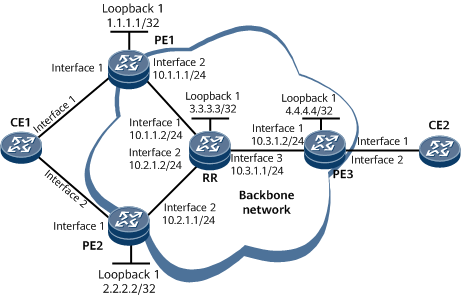
On the network shown in Figure 1, PE1, PE2, the RR, and PE3 belong to the same AS. They need to communicate with each other using OSPF, and MPLS tunnels need to be deployed to carry EVPN VPWS services. CE1 is dual-homed to PE1 and PE2 in single-active mode. PE1 is the active PE, and PE2 is the standby PE. CE2 is single-homed to PE3.

Configuration Roadmap
The configuration roadmap is as follows:
Configure an IGP on the backbone network to allow PEs and the RR to communicate.
Configure basic MPLS functions and enable MPLS LDP to establish LDP LSPs on the backbone network.
Configure EVPN VPWS and EVPL instances on each PE and bind the EVPL instance to an access-side sub-interface.
- Configure an E-Trunk on each PE to implement the EVPN single-active mode.
Establish BGP EVPN peer relationships between PEs and the RR. On the RR, configure the PEs as RR clients.
Configure FRR on PEs.
Data Preparation
To complete the configuration, you need the following data:
EVPN instance name: evrf1
EVPN instance RDs: 100:1, 100:2, and 100:3; RTs: 1:1
Procedure
- Configure interface addresses on the RR and PEs according to Figure 1. For configuration details, see Configuration Files in this section.
- Configure an IGP on the backbone network to allow PEs and the RR to communicate. OSPF is used as the IGP in this example.
# Configure PE1.
[~PE1] ospf 1
[*PE1-ospf-1] area 0
[*PE1-ospf-1-area-0.0.0.0] network 10.1.1.0 0.0.0.255
[*PE1-ospf-1-area-0.0.0.0] network 1.1.1.1 0.0.0.0
[*PE1-ospf-1-area-0.0.0.0] commit
[~PE1-ospf-1-area-0.0.0.0] quit
[~PE1-ospf-1] quit
# Configure PE2.
[~PE2] ospf 1
[*PE2-ospf-1] area 0
[*PE2-ospf-1-area-0.0.0.0] network 10.2.1.0 0.0.0.255
[*PE2-ospf-1-area-0.0.0.0] network 2.2.2.2 0.0.0.0
[*PE2-ospf-1-area-0.0.0.0] commit
[~PE2-ospf-1-area-0.0.0.0] quit
[~PE2-ospf-1] quit
# Configure PE3.
[~PE3] ospf 1
[*PE3-ospf-1] area 0
[*PE3-ospf-1-area-0.0.0.0] network 10.3.1.0 0.0.0.255
[*PE3-ospf-1-area-0.0.0.0] network 4.4.4.4 0.0.0.0
[*PE3-ospf-1-area-0.0.0.0] commit
[~PE3-ospf-1-area-0.0.0.0] quit
[~PE3-ospf-1] quit
# Configure the RR.
[~RR] ospf 1
[*RR-ospf-1] area 0
[*RR-ospf-1-area-0.0.0.0] network 10.1.1.0 0.0.0.255
[*RR-ospf-1-area-0.0.0.0] network 10.2.1.0 0.0.0.255
[*RR-ospf-1-area-0.0.0.0] network 10.3.1.0 0.0.0.255
[*RR-ospf-1-area-0.0.0.0] network 3.3.3.3 0.0.0.0
[*RR-ospf-1-area-0.0.0.0] commit
[~RR-ospf-1-area-0.0.0.0] quit
[~RR-ospf-1] quit
- Configure basic MPLS functions and enable MPLS LDP to establish LDP LSPs on the MPLS backbone network.
# Configure PE1.
[~PE1] mpls lsr-id 1.1.1.1
[*PE1] mpls
[*PE1-mpls] quit
[*PE1] mpls ldp
[*PE1-mpls-ldp] quit
[*PE1] interface gigabitethernet 0/1/8
[*PE1-GigabitEthernet0/1/8] mpls
[*PE1-GigabitEthernet0/1/8] mpls ldp
[*PE1-GigabitEthernet0/1/8] commit
[~PE1-GigabitEthernet0/1/8] quit
# Configure PE2.
[~PE2] mpls lsr-id 2.2.2.2
[*PE2] mpls
[*PE2-mpls] quit
[*PE2] mpls ldp
[*PE2-mpls-ldp] quit
[*PE2] interface gigabitethernet 0/1/8
[*PE2-GigabitEthernet0/1/8] mpls
[*PE2-GigabitEthernet0/1/8] mpls ldp
[*PE2-GigabitEthernet0/1/8] commit
[~PE2-GigabitEthernet0/1/8] quit
# Configure the RR.
[~RR] mpls lsr-id 3.3.3.3
[*RR] mpls
[*RR-mpls] quit
[*RR] mpls ldp
[*RR-mpls-ldp] quit
[*RR] interface gigabitethernet 0/1/0
[*RR-GigabitEthernet0/1/0] mpls
[*RR-GigabitEthernet0/1/0] mpls ldp
[*RR-GigabitEthernet0/1/0] quit
[*RR] interface gigabitethernet 0/1/8
[*RR-GigabitEthernet0/1/8] mpls
[*RR-GigabitEthernet0/1/8] mpls ldp
[*RR-GigabitEthernet0/1/8] quit
[*RR] interface gigabitethernet 0/1/16
[*RR-GigabitEthernet0/1/16] mpls
[*RR-GigabitEthernet0/1/16] mpls ldp
[*RR-GigabitEthernet0/1/16] commit
[~RR-GigabitEthernet0/1/16] quit
# Configure PE3.
[~PE3] mpls lsr-id 4.4.4.4
[*PE3] mpls
[*PE3-mpls] quit
[*PE3] mpls ldp
[*PE3-mpls-ldp] quit
[*PE3] interface gigabitethernet 0/1/0
[*PE3-GigabitEthernet0/1/0] mpls
[*PE3-GigabitEthernet0/1/0] mpls ldp
[*PE3-GigabitEthernet0/1/0] commit
[~PE3-GigabitEthernet0/1/0] quit
- Configure EVPN VPWS and EVPL instances on each PE and bind the EVPL instance to an access-side sub-interface.
# Configure PE1.
[~PE1] evpn vpn-instance evrf1 vpws
[*PE1-vpws-evpn-instance-evrf1] route-distinguisher 100:1
[*PE1-vpws-evpn-instance-evrf1] vpn-target 1:1
[*PE1-vpws-evpn-instance-evrf1] quit
[*PE1] evpl instance 1
[*PE1-evpl1] evpn binding vpn-instance evrf1
[*PE1-evpl1] local-service-id 100 remote-service-id 200
[*PE1-evpl1] quit
[*PE1] interface Eth-Trunk1
[*PE1-Eth-Trunk1] mode lacp-static
[*PE1-Eth-Trunk1] esi 0001.0002.0003.0004.0005
[*PE1-Eth-Trunk1] quit
[*PE1] interface gigabitethernet 0/1/0
[*PE1-GigabitEthernet 0/1/0] eth-trunk 1
[*PE1-GigabitEthernet 0/1/0] quit
[*PE1] interface Eth-Trunk1.1
[*PE1-Eth-Trunk1.1] vlan-type dot1q 1
[*PE1-Eth-Trunk1.1] evpl instance 1
[*PE1-Eth-Trunk1.1] quit
[*PE1] commit
# Configure PE2.
[~PE2] evpn vpn-instance evrf1 vpws
[*PE2-vpws-evpn-instance-evrf1] route-distinguisher 100:2
[*PE2-vpws-evpn-instance-evrf1] vpn-target 1:1
[*PE2-vpws-evpn-instance-evrf1] quit
[*PE2] evpl instance 1
[*PE2-evpl1] evpn binding vpn-instance evrf1
[*PE2-evpl1] local-service-id 100 remote-service-id 200
[*PE2-evpl1] quit
[*PE2] interface Eth-Trunk1
[*PE2-Eth-Trunk1] mode lacp-static
[*PE2-Eth-Trunk1] esi 0001.0002.0003.0004.0005
[*PE2-Eth-Trunk1] quit
[*PE2] interface gigabitethernet 0/1/0
[*PE2-GigabitEthernet 0/1/0] eth-trunk 1
[*PE2-GigabitEthernet 0/1/0] quit
[*PE2] interface Eth-Trunk1.1
[*PE2-Eth-Trunk1.1] vlan-type dot1q 1
[*PE2-Eth-Trunk1.1] evpl instance 1
[*PE2-Eth-Trunk1.1] quit
[*PE2] commit
# Configure PE3.
[~PE3] evpn vpn-instance evrf1 vpws
[*PE3-vpws-evpn-instance-evrf1] route-distinguisher 100:3
[*PE3-vpws-evpn-instance-evrf1] vpn-target 1:1
[*PE3-vpws-evpn-instance-evrf1] quit
[*PE3] evpl instance 1
[*PE3-evpl1] evpn binding vpn-instance evrf1
[*PE3-evpl1] local-service-id 200 remote-service-id 100
[*PE3-evpl1] quit
[*PE3] interface gigabitethernet 0/1/8
[*PE3-GigabitEthernet 0/1/8] evpl instance 1
[*PE3-GigabitEthernet 0/1/8] quit
[*PE3] commit
- Configure a source address on each PE.
# Configure PE1.
[~PE1] evpn source-address 1.1.1.1
[*PE1] commit
# Configure PE2.
[~PE2] evpn source-address 2.2.2.2
[*PE2] commit
# Configure PE3.
[~PE3] evpn source-address 4.4.4.4
[*PE3] commit
- Configure an E-Trunk on each PE to implement the EVPN single-active mode.
# Configure PE1.
[~PE1] evpn redundancy-mode single-active
[*PE1] lacp e-trunk system-id 00e0-fc00-0001
[*PE1] e-trunk 1
[*PE1-e-trunk-1] priority 10
[*PE1-e-trunk-1] peer-address 2.2.2.2 source-address 1.1.1.1
[*PE1-e-trunk-1] security-key cipher 00E0FC000000
[*PE1-e-trunk-1] quit
[*PE1] interface Eth-Trunk1
[*PE1-Eth-Trunk1] e-trunk 1
[*PE1-Eth-Trunk1] quit
[*PE1] commit
# Configure PE2.
[~PE2] evpn redundancy-mode single-active
[*PE2] lacp e-trunk system-id 00e0-fc00-0001
[*PE2] e-trunk 1
[*PE2-e-trunk-1] priority 20
[*PE2-e-trunk-1] peer-address 1.1.1.1 source-address 2.2.2.2
[*PE2-e-trunk-1] security-key cipher 00E0FC000000
[*PE2-e-trunk-1] quit
[*PE2] interface Eth-Trunk1
[*PE2-Eth-Trunk1] e-trunk 1
[*PE2-Eth-Trunk1] quit
[*PE2] commit
- Establish BGP EVPN peer relationships between PEs and the RR. On the RR, configure the PEs as RR clients.
# Configure PE1.
[~PE1] bgp 100
[*PE1-bgp] peer 3.3.3.3 as-number 100
[*PE1-bgp] peer 3.3.3.3 connect-interface loopback 1
[*PE1-bgp] l2vpn-family evpn
[*PE1-bgp-af-evpn] peer 3.3.3.3 enable
[*PE1-bgp-af-evpn] quit
[*PE1-bgp] quit
[*PE1] commit
# Configure PE2.
[~PE2] bgp 100
[*PE2-bgp] peer 3.3.3.3 as-number 100
[*PE2-bgp] peer 3.3.3.3 connect-interface loopback 1
[*PE2-bgp] l2vpn-family evpn
[*PE2-bgp-af-evpn] peer 3.3.3.3 enable
[*PE2-bgp-af-evpn] quit
[*PE2-bgp] quit
[*PE2] commit
# Configure PE3.
[~PE3] bgp 100
[*PE3-bgp] peer 3.3.3.3 as-number 100
[*PE3-bgp] peer 3.3.3.3 connect-interface loopback 1
[*PE3-bgp] l2vpn-family evpn
[*PE3-bgp-af-evpn] peer 3.3.3.3 enable
[*PE3-bgp-af-evpn] quit
[*PE3-bgp] quit
[*PE3] commit
# Configure the RR.
[~RR] bgp 100
[*RR-bgp] peer 1.1.1.1 as-number 100
[*RR-bgp] peer 1.1.1.1 connect-interface loopback 1
[*RR-bgp] peer 2.2.2.2 as-number 100
[*RR-bgp] peer 2.2.2.2 connect-interface loopback 1
[*RR-bgp] peer 4.4.4.4 as-number 100
[*RR-bgp] peer 4.4.4.4 connect-interface loopback 1
[*RR-bgp] l2vpn-family evpn
[*RR-bgp-af-evpn] undo policy vpn-target
[*RR-bgp-af-evpn] peer 1.1.1.1 enable
[*RR-bgp-af-evpn] peer 1.1.1.1 reflect-client
[*RR-bgp-af-evpn] peer 2.2.2.2 enable
[*RR-bgp-af-evpn] peer 2.2.2.2 reflect-client
[*RR-bgp-af-evpn] peer 4.4.4.4 enable
[*RR-bgp-af-evpn] peer 4.4.4.4 reflect-client
[*RR-bgp-af-evpn] quit
[*RR-bgp] quit
[*RR] commit
After completing the configurations, run the display bgp evpn peer command on the RR. The command output shows that BGP peer relationships have been established between the PEs and RR and are in the Established state.
[~RR] display bgp evpn peer BGP local router ID : 3.3.3.3 Local AS number : 100 Total number of peers : 3 Peers in established state : 3 Peer V AS MsgRcvd MsgSent OutQ Up/Down State PrefRcv 1.1.1.1 4 100 9 15 0 00:03:41 Established 1 2.2.2.2 4 100 9 15 0 00:03:42 Established 1 4.4.4.4 4 100 8 15 0 00:03:42 Established 1 - Configure FRR on PEs.
# Configure PE1.
[~PE1] evpn vpn-instance evrf1 vpws
[*PE1-vpws-evpn-instance-evrf1] local-remote frr enable
[*PE1-vpws-evpn-instance-evrf1] quit
[*PE1] commit
# Configure PE2.
[~PE2] evpn vpn-instance evrf1 vpws
[*PE2-vpws-evpn-instance-evrf1] local-remote frr enable
[*PE2-vpws-evpn-instance-evrf1] quit
[*PE2] commit
# Configure PE3.
[~PE3] evpn vpn-instance evrf1 vpws
[*PE3-vpws-evpn-instance-evrf1] remote frr enable
[*PE3-vpws-evpn-instance-evrf1] quit
[*PE3] commit
- Verify the configuration.
Run the display bgp evpn vpn-instance evrf1 routing-table ad-route 0001.0002.0003.0004.0005:100 command on PE3. The command output shows detailed information about the EVPN Ethernet A-D routes sent by PE1 and PE2. The route sent by PE1 is selected, and the route sent by PE2 is a backup route. In addition, you can view the label information about the bypass tunnel after FRR is configured.
[~PE3] display bgp evpn vpn-instance evrf1 routing-table ad-route 0001.0002.0003.0004.0005:100
 BGP local router ID : 4.4.4.4
 Local AS number : 100

 EVPN-Instance evrf1:
 Number of A-D Routes: 2
 BGP routing table entry information of 0001.0002.0003.0004.0005:100:
 Route Distinguisher: 100:1
 Remote-Cross route
 Label information (Received/Applied): 48123/NULL
 From: 3.3.3.3 (3.3.3.3)
 Route Duration: 0d00h21m10s
 Relay Tunnel Out-Interface: GigabitEthernet0/1/0
 Original nexthop: 1.1.1.1
 Qos information : 0x0
 Ext-Community: RT <1 : 1>, SoO <1.1.1.1 : 0>, EVPN L2 Attributes <MTU:1500 C:0 P:1 B:0>, Bypass Label<0 : 0 : 48124>
 AS-path Nil, origin incomplete, localpref 100, pref-val 0, valid, internal, best, select, pre 255, IGP cost 2
 Originator: 1.1.1.1
 Cluster list: 3.3.3.3
 Route Type: 1 (Ethernet Auto-Discovery (A-D) route)
 ESI: 0001.0002.0003.0004.0005, Ethernet Tag ID: 100
 Not advertised to any peer yet

 BGP routing table entry information of 0001.0002.0003.0004.0005:100:
 Route Distinguisher: 100:2
 Remote-Cross route
 Label information (Received/Applied): 48123/NULL
 From: 3.3.3.3 (3.3.3.3)
 Route Duration: 0d00h20m53s
 Relay Tunnel Out-Interface: GigabitEthernet0/1/0
 Original nexthop: 2.2.2.2
 Qos information : 0x0
 Ext-Community: RT <1 : 1>, SoO <2.2.2.2 : 0>, EVPN L2 Attributes <MTU:1500 C:0 P:0 B:1>, Bypass Label<0 : 0 : 48124>
 AS-path Nil, origin incomplete, localpref 100, pref-val 0, valid, internal, backup, pre 255, IGP cost 2, not preferred for L2 ext-community
 Originator: 2.2.2.2
 Cluster list: 3.3.3.3
 Route Type: 1 (Ethernet Auto-Discovery (A-D) route)
 ESI: 0001.0002.0003.0004.0005, Ethernet Tag ID: 100
 Not advertised to any peer yet
Configuration Files
PE1 configuration file
#
sysname PE1
#
lacp e-trunk system-id 00e0-fc00-0001
#
evpn redundancy-mode single-active
#
e-trunk 1
 priority 10
 peer-address 2.2.2.2 source-address 1.1.1.1
 security-key cipher %^%#!8C!"bAoc~O}UW2)%$HP4%.G9179.;&Yr[GmV.PN%^%#
 authentication-mode enhanced-hmac-sha256
#
evpn vpn-instance evrf1 vpws
 route-distinguisher 100:1
 local-remote frr enable
 vpn-target 1:1 export-extcommunity
 vpn-target 1:1 import-extcommunity
#
evpl instance 1
 evpn binding vpn-instance evrf1
 local-service-id 100 remote-service-id 200
#
mpls lsr-id 1.1.1.1
#
mpls
#
mpls ldp
#
interface Eth-Trunk1
 mode lacp-static
 e-trunk 1
 esi 0001.0002.0003.0004.0005
#
interface Eth-Trunk1.1
 vlan-type dot1q 1
 evpl instance 1
#
interface GigabitEthernet0/1/0
 undo shutdown
 eth-trunk 1
#
interface GigabitEthernet0/1/8
 undo shutdown
 ip address 10.1.1.1 255.255.255.0
 mpls
 mpls ldp
#
interface LoopBack1
 ip address 1.1.1.1 255.255.255.255
#
bgp 100
 peer 3.3.3.3 as-number 100
 peer 3.3.3.3 connect-interface LoopBack1
 #
 ipv4-family unicast
  undo synchronization
  peer 3.3.3.3 enable
 #
 l2vpn-family evpn
  policy vpn-target
  peer 3.3.3.3 enable
#
ospf 1
 area 0.0.0.0
  network 1.1.1.1 0.0.0.0
  network 10.1.1.0 0.0.0.255
#
evpn source-address 1.1.1.1
#
return
PE2 configuration file
#
sysname PE2
#
lacp e-trunk system-id 00e0-fc00-0001
#
evpn redundancy-mode single-active
#
e-trunk 1
 priority 20
 peer-address 1.1.1.1 source-address 2.2.2.2
 security-key cipher %^%#GAG\Y-F%GY[GnwCkov7A<e(m/cl}m86`jd6z[79~%^%#
 authentication-mode enhanced-hmac-sha256
#
evpn vpn-instance evrf1 vpws
 route-distinguisher 100:2
 local-remote frr enable
 vpn-target 1:1 export-extcommunity
 vpn-target 1:1 import-extcommunity
#
evpl instance 1
 evpn binding vpn-instance evrf1
 local-service-id 100 remote-service-id 200
#
mpls lsr-id 2.2.2.2
#
mpls
#
mpls ldp
#
interface Eth-Trunk1
 mode lacp-static
 e-trunk 1
 esi 0001.0002.0003.0004.0005
#
interface Eth-Trunk1.1
 vlan-type dot1q 1
 evpl instance 1
#
interface GigabitEthernet0/1/0
 undo shutdown
 eth-trunk 1
#
interface GigabitEthernet0/1/8
 undo shutdown
 ip address 10.2.1.1 255.255.255.0
 mpls
 mpls ldp
#
interface LoopBack1
 ip address 2.2.2.2 255.255.255.255
#
bgp 100
 peer 3.3.3.3 as-number 100
 peer 3.3.3.3 connect-interface LoopBack1
 #
 ipv4-family unicast
  undo synchronization
  peer 3.3.3.3 enable
 #
 l2vpn-family evpn
  policy vpn-target
  peer 3.3.3.3 enable
#
ospf 1
 area 0.0.0.0
  network 2.2.2.2 0.0.0.0
  network 10.2.1.0 0.0.0.255
#
evpn source-address 2.2.2.2
#
return
PE3 configuration file
#
sysname PE3
#
evpn redundancy-mode single-active
#
evpn vpn-instance evrf1 vpws
 route-distinguisher 100:3
 remote frr enable
 vpn-target 1:1 export-extcommunity
 vpn-target 1:1 import-extcommunity
#
evpl instance 1
 evpn binding vpn-instance evrf1
 local-service-id 200 remote-service-id 100
#
mpls lsr-id 4.4.4.4
#
mpls
#
mpls ldp
#
interface GigabitEthernet0/1/0
 undo shutdown
 ip address 10.3.1.2 255.255.255.0
 mpls
 mpls ldp
#
interface GigabitEthernet0/1/8
 undo shutdown
 evpl instance 1
#
interface LoopBack1
 ip address 4.4.4.4 255.255.255.255
#
bgp 100
 peer 3.3.3.3 as-number 100
 peer 3.3.3.3 connect-interface LoopBack1
 #
 ipv4-family unicast
  undo synchronization
  peer 3.3.3.3 enable
 #
 l2vpn-family evpn
  policy vpn-target
  peer 3.3.3.3 enable
#
ospf 1
 area 0.0.0.0
  network 4.4.4.4 0.0.0.0
  network 10.3.1.0 0.0.0.255
#
evpn source-address 4.4.4.4
#
return
RR configuration file
#
sysname RR
#
mpls lsr-id 3.3.3.3
#
mpls
#
mpls ldp
#
interface GigabitEthernet0/1/8
 undo shutdown
 ip address 10.2.1.2 255.255.255.0
 mpls
 mpls ldp
#
interface GigabitEthernet0/1/0
 undo shutdown
 ip address 10.1.1.2 255.255.255.0
 mpls
 mpls ldp
#
interface GigabitEthernet0/1/16
 undo shutdown
 ip address 10.3.1.1 255.255.255.0
 mpls
 mpls ldp
#
interface LoopBack1
 ip address 3.3.3.3 255.255.255.255
#
bgp 100
 peer 1.1.1.1 as-number 100
 peer 1.1.1.1 connect-interface LoopBack1
 peer 2.2.2.2 as-number 100
 peer 2.2.2.2 connect-interface LoopBack1
 peer 4.4.4.4 as-number 100
 peer 4.4.4.4 connect-interface LoopBack1
 #
 ipv4-family unicast
  undo synchronization
  peer 1.1.1.1 enable
  peer 2.2.2.2 enable
  peer 4.4.4.4 enable
 #
 l2vpn-family evpn
  undo policy vpn-target
  peer 1.1.1.1 enable
  peer 1.1.1.1 reflect-client
  peer 2.2.2.2 enable
  peer 2.2.2.2 reflect-client
  peer 4.4.4.4 enable
  peer 4.4.4.4 reflect-client
#
ospf 1
 area 0.0.0.0
  network 3.3.3.3 0.0.0.0
  network 10.1.1.0 0.0.0.255
  network 10.2.1.0 0.0.0.255
  network 10.3.1.0 0.0.0.255
#
return
- CE1 configuration file
#
sysname CE1
#
interface Eth-Trunk1
 mode lacp-static
#
interface GigabitEthernet0/1/0
 undo shutdown
 eth-trunk 1
#
interface GigabitEthernet0/1/8
 undo shutdown
 eth-trunk 1
#
- CE2 configuration file
#
sysname CE2
#
interface GigabitEthernet0/1/0
 undo shutdown
#