IGMP Snooping over EVPN MPLS
If the Ethernet virtual private network (EVPN) function is deployed on a network to carry multicast services but Internet Group Management Protocol (IGMP) snooping is not configured on PEs, multicast data packets are broadcast on the network. The devices that do not need to receive the multicast data packets also receive these packets, which wastes network bandwidth resources. To resolve this issue, deploy IGMP snooping over EVPN Multiprotocol Label Switching (MPLS). After IGMP snooping over EVPN MPLS is deployed, IGMP snooping packets are transmitted on the network through EVPN routes, and multicast forwarding entries are generated on devices. Multicast data packets from a multicast source are advertised only to the devices that need these packets, saving network bandwidth resources.
For details about EVPN routes used by IGMP snooping over EVPN MPLS, see Related Routes. For details about route advertisement and traffic forwarding, see Route Advertisement and Traffic Forwarding.
Related Routes
SMET route
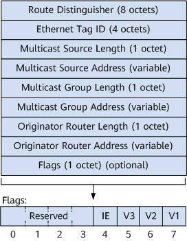
SMET routes are used to transmit multicast group information between BGP EVPN peers. A device that receives an SMET route can construct local (*, G) or (S, G) entries based on the routing information. As shown in Figure 1, the fields in the routing information are described as follows:Route Distinguisher: RD configured in an EVPN instance.
Ethernet Tag ID: This field is set to 0 when the VLAN-based or VLAN bundle service mode is used to access a user network.
Multicast Source Length: length of a multicast source address. This field is set to 0 for any multicast source.
Multicast Source Address: address of a multicast source. Packets do not contain this field for any multicast source.
Multicast Group Length: length of a multicast group address.
Multicast Group Address: address of a multicast group.
Originator Router Length: address length of the device that generated the SMET route.
Originator Router Address: address of the device that generated the SMET route.
Flags: This field contains 8 bits. The first 4 most significant bits are reserved, and the last 3 least significant bits are used to identify IGMP versions. If bit 5 is set to 1, the IGMP version of the multicast entry carried in the route is IGMPv3. Only one of these 3 bits can be set to 1. Bit 4 indicates the filtering mode of group records in IGMPv3. The values 0 and 1 indicate Include and Exclude group types, respectively.
IGMP Join Synch route
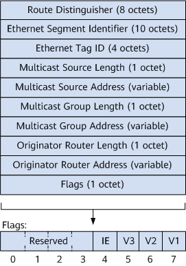
IGMP Join Synch routes are used to synchronize multicast group join information between dual-homed devices on the access side. A device that receives an IGMP Join Synch route can add member entries to the local (S, G) entries based on the routing information, ensuring that the local entries are the same as those on the device connected to the same user network. As shown in Figure 2, the fields in the routing information are described as follows:Route Distinguisher: route distinguisher (RD) configured in an EVPN instance.
Ethernet Segment Identifier: unique identifier defined for a device to connect to the access network.
Ethernet Tag ID: This field is set to 0 when the VLAN-based or VLAN bundle service mode is used to access a user network.
Multicast Source Length: length of a multicast source address. This field is set to 0 for any multicast source.
Multicast Source Address: address of a multicast source. Packets do not contain this field for any multicast source.
Multicast Group Length: length of a multicast group address.
Multicast Group Address: address of a multicast group.
Originator Router Length: address length of the device that generated the IGMP Join Synch route.
Originator Router Address: address of the device that generated the IGMP Join Synch route.
Flags: This field contains 8 bits. The first 4 most significant bits are reserved, and the last 3 least significant bits are used to identify IGMP versions. If bit 5 is set to 1, the IGMP version of the multicast entry carried in the route is IGMPv3. Only one of these 3 bits can be set to 1. Bit 4 indicates the filtering mode of group records in IGMPv3. The values 0 and 1 indicate Include and Exclude group types, respectively.
Route Advertisement and Traffic Forwarding
IGMP snooping over EVPN MPLS supports single- and dual-homing access.
Single-homing access for IGMP snooping over EVPN MPLS
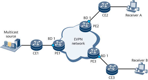
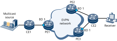
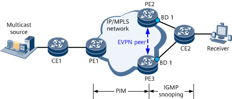
Figure 3 shows single-homing access for IGMP snooping over EVPN MPLS. Configure an EVPN instance on PE1, PE2, and PE3, and bind a BD to the EVPN instance. Establish BGP EVPN peer relationships between the PEs, and deploy EVPN IGMP proxy on each PE. Deploy PE1 as a sender PE, and deploy PE2 and PE3 as receiver PEs. Configure IGMP snooping and IGMP proxy on BD1 bound to the EVPN instance on PE1, PE2, and PE3. Connect BD1 on PE1, PE2, and PE3 to CE1, CE2, and CE3 through VLAN dot1q sub-interfaces, respectively. Configure PIM-SM on CE1's interface connected to a multicast source and IGMP on CE1's interface connected to PE1.
PE1, PE2, and PE3 periodically send IGMP Query messages to the access side in BD1.
Receiver A and Receiver B send IGMP Report messages to CE2 and CE3, respectively. For example, Receiver A sends an IGMPv3 (S, G) Report message, and Receiver B sends an IGMPv2 (*, G) Report message.
After receiving the corresponding IGMP Report messages, PE2 and PE3 establish (S, G) and (*, G) entries of IGMP snooping in BD1 and add the interfaces connected to CE2 and CE3 as outbound interfaces, respectively.
PE2 sends a BGP EVPN SMET route to the other PEs through BGP EVPN peer relationships. The route carries (S, G) entries, and the Flags field in the route is set to IGMPv3 and Include.
PE3 sends a BGP EVPN SMET route to the other PEs through BGP EVPN peer relationships. The route carries (*, G) entries, and the Flags field in the route is set to IGMPv2.
After receiving the corresponding BGP EVPN SMET routes, PE1 establishes (S, G) and (*, G) entries of IGMP snooping in BD1 and adds the mLDP tunnel interfaces of the corresponding EVPN instances as outbound interfaces.
PE1 sends IGMPv3 (S, G) Report and IGMPv2 (*, G) Report messages to CE1. CE1 establishes IGMP and PIM entries and forwards multicast traffic to PE1.
After receiving the multicast traffic, PE1 forwards the traffic to PE2 and PE3 through the mLDP tunnel interfaces based on the (S, G) and (*, G) entries in BD1.
After receiving the multicast traffic, PE2 and PE3 forward the traffic to Receiver A and Receiver B based on the (S, G) and (*, G) entries, respectively.
Dual-homing access for IGMP snooping over EVPN MPLS on the multicast source side
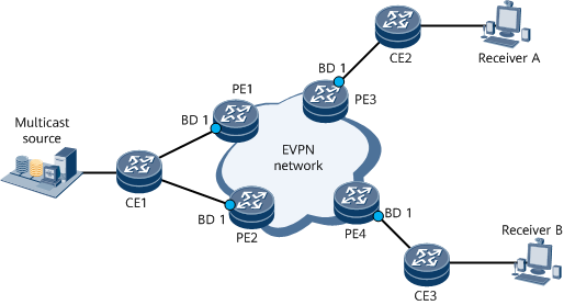
Figure 4 shows dual-homing access for IGMP snooping over EVPN MPLS on the multicast source side. Configure an EVPN instance on PE1, PE2, PE3, and PE4, and bind a BD to the EVPN instance. Establish BGP EVPN peer relationships between the PEs, and deploy EVPN IGMP proxy on each PE. Deploy PE1 and PE2 as sender PEs, and deploy PE3 and PE4 as receiver PEs. Connect BD1 on PE3 and PE4 to CE3 and CE4 through VLAN dot1q sub-interfaces, respectively. Connect CE1 to PE1 and PE2 through Eth-Trunk interfaces, and configure PIM-SM and IGMP on the interfaces. Bind the Eth-Trunk interfaces of CE1 to an E-Trunk on PE1 and PE2. Configure static router interfaces, and set the same ESI. Configure the E-Trunk to work in dual-active mode, and ensure that the Eth-Trunk interfaces on PE1 and PE2 are both Up.
PE3 and PE4 periodically send IGMP Query messages to the access side in BD1.
Receiver A and Receiver B send IGMP Report messages to CE2 and CE3, respectively. For example, Receiver A sends an IGMPv3 (S, G) Report message, and Receiver B sends an IGMPv2 (*, G) Report message.
After receiving the corresponding IGMP Report messages, PE3 and PE4 establish (S, G) and (*, G) entries of IGMP snooping in BD1 and add the interfaces connected to CE2 and CE3 as outbound interfaces, respectively.
PE3 sends a BGP EVPN SMET route to the other PEs through BGP EVPN peer relationships. The route carries (S, G) entries, and the Flags field in the route is set to IGMPv3 and Include.
PE4 sends a BGP EVPN SMET route to the other PEs through BGP EVPN peer relationships. The route carries (*, G) entries, and the Flags field in the route is set to IGMPv2.
After receiving the corresponding BGP EVPN SMET routes, PE1 and PE2 establish (S, G) and (*, G) entries of IGMP snooping in BD1 and add the mLDP tunnel interfaces of the corresponding EVPN instances as outbound interfaces.
The Eth-Trunk interface of CE1 periodically sends IGMP Query messages to BD1 of PE1 or PE2 based on hash rules. PE1 or PE2 periodically sends IGMP Report messages to CE1.
After receiving an IGMP Report message, CE1 creates IGMP and PIM entries and forwards multicast traffic to PE1.
CE1 forwards the multicast traffic from the multicast source to BD1 of PE1 or PE2 based on hash rules. PE1 or PE2 forwards the multicast traffic to PE3 and PE4 through the mLDP tunnel interfaces based on the (*, G) and (S, G) entries of BD1.
After receiving the multicast traffic, PE2 and PE3 forward the traffic to Receiver A and Receiver B based on the (S, G) and (*, G) entries, respectively.
Dual-homing access for IGMP snooping over EVPN MPLS on the access side
Figure 5 shows dual-homing access for IGMP snooping over EVPN MPLS on the access side. Configure an EVPN instance on PE1, PE2, and PE3, and bind a BD to the EVPN instance. Establish BGP EVPN peer relationships between the PEs, and deploy EVPN IGMP proxy on each PE. Deploy PE1 as a sender PE, and deploy PE2 and PE3 as receiver PEs. Configure IGMP snooping and IGMP proxy on BD1 bound to the EVPN instance on PE1, PE2, and PE3. Connect BD1 on PE1, PE2, and PE3 to CE1, CE2, and CE3 through VLAN dot1q sub-interfaces, respectively. Configure PIM-SM and IGMP on CE1's interface connected to PE1, and connect CE2 to PE2 and PE3 through Eth-Trunk interfaces. Bind the Eth-Trunk interfaces of CE2 to an E-Trunk and configure the same ESI on PE2 and PE3. Configure the E-Trunk on PE2 and PE3 to work in single-active mode, select PE2 as the master device, and ensure that the Eth-Trunk interface of PE2 is up.

IGMPv3 is not supported in access-side dual-homing access scenarios.
PE2 periodically sends IGMP Query messages to the access side in BD1.
The receiver sends an IGMP Report message, for example, IGMPv2 (*, G) Report message, to CE2.
After receiving an IGMP Report message, PE2 establishes (*, G) entries of IGMP snooping, adds the Eth-Trunk interface to CE2 as the outbound interface, and sends the IGMP Join Synch route of BGP EVPN to other PEs. The route carries the access-side ESI of PE2 and contains the IGMP version and source filtering mode.
After receiving the IGMP Join Synch route, PE3 creates the corresponding (*, G) entries of IGMP snooping in BD1. PE3 does not need to send a BGP EVPN SMET route, because it is a non-DF. Additionally, PE3 does not add the Eth-Trunk interface to CE2 as the outbound interface, because the Eth-Trunk interface is down.
PE2 functioning as a DF sends a BGP EVPN SMET route based on (*, G) entries of IGMP snooping.
After receiving the BGP EVPN SMET route from PE2, PE1 creates (*, G) entries of IGMP snooping and sends an IGMP Report message to CE1.
After receiving an IGMP Report message, CE1 creates IGMP and PIM entries and forwards multicast traffic to PE1.
CE1 sends the multicast traffic received from the multicast source to PE1.
After receiving the multicast traffic, PE1 forwards the traffic to PE2 and PE3 through the mLDP tunnel interfaces based on the (*, G) entries in BD1.
After PE2 and PE3 receive the multicast traffic, PE2 forwards the traffic to CE2 based on the (*, G) entries, but PE3 does not. In this case, the receiver receives only one copy of multicast traffic.
If some receivers are disconnected or do not need to receive multicast traffic, PE2 updates the (*, G) entry based on the IGMP Report message received from CE2 and then sends an IGMP Join Synch route withdraw message to PE3. This ensures that PE3 deletes the (*, G) entry corresponding to the receiver, so that the (*, G) entry on PE3 is the same as that on PE2.
If the access side of PE2 fails, the EVPN instance selects PE3 as a DF, and the Eth-Trunk interface of PE3 goes up. PE3 then adds the Eth-Trunk interface to CE2 as the outbound interface, so that multicast traffic is forwarded from PE3 to CE2.
IGMP snooping over EVPN MPLS access-side dual-homing access (Layer 2 to Layer 3 in active-active mode)
As shown in Figure 6, CE2 is dual-homed to PE2 and PE3 on the IGMP Snooping over EVPN MPLS access side. Configure PE1 as a sender PE and PE2 and PE3 as receiver PEs. Configure PIM-SM on PE1, PE2, and PE3. Configure an EVPN instance on PE2 and PE3, bind BD1 to the EVPN instance, create VBDIF1 for BD1, and enable PIM-SM and IGMP on VBDIF1. IGMP snooping and IGMP snooping proxy are automatically enabled in BD1. Establish a BGP EVPN peer relationship between PE2 and PE3. CE1 is connected to PE1 through a common Layer 3 interface, and CE2 is connected to PE2 and PE3 through Eth-Trunk interfaces. Bind the Eth-Trunk interfaces of CE2 to an E-Trunk and configure the same ESI on PE2 and PE3. The E-Trunks on PE2 and PE3 are configured to work in active-active mode, and the Eth-Trunks on PE2 and PE3 are both up. In this example, PE2 is selected as the DF, and PE3 is not selected as the DF.
In a scenario of dual-homing access for IGMP snooping over EVPN on the access side, devices are dual-homed to receivers, and Layer 2 multicast services access Layer 3 multicast services. Then the IGMP snooping over EVPN MPLS working process is as follows:
PE2 and PE3 periodically send IGMP Query messages to the access side in BD1.
The receiver sends an IGMP Report message, for example, IGMPv2 (*, G) Report message, to CE2. CE2's Eth-Trunk connected to PE2 and PE3 is up. CE2 sends an IGMP Report message to PE2 or PE3 based on the hash rule.
Upon receipt of the IGMP Report message, PE2 or PE3 creates an IGMP snooping (*, G) entry and sends an IGMP Join Synch route to each other. The IGMP Join Synch route carries the ESI on the access side of PE2 or PE3, in addition, the IGMP version and source filtering mode are included.
After PE2 or PE3 receives the IGMP Join Synch route, it creates an IGMP snooping (*, G) entry in BD1. PE2 functions as a DF to advertise Layer 3 IGMP (*, G) entries to VBDIF1 and uses the Eth-Trunk interface connected to CE2 as an outbound interface. As a non-DF device, PE3 does not need to advertise Layer 3 IGMP (*, G) entries to VBDIF1 or use the Eth-Trunk connected to CE2 as an outbound interface.
PE2 creates a Layer 3 PIM (*, G) entry, adds VBDIF1 as an outbound interface, and sends a PIM Join message to PE1.
After receiving the PIM Join message from PE2, PE1 creates an IGMP (*, G) entry and sends an IGMP Report message to CE1.
After receiving an IGMP Report message, CE1 creates IGMP and PIM entries and forwards multicast traffic to PE1.
CE1 sends the multicast traffic received from the multicast source to PE1.
After receiving the multicast traffic, PE1 forwards the (*, G) entry to PE2 and PE3 through the mLDP tunnel interfaces.
After PE2 and PE3 receive the multicast traffic, PE2 forwards the traffic to CE2 based on the (*, G) entries, but PE3 does not. In this case, the receiver receives only one copy of multicast traffic.
If some receivers are disconnected or do not need to receive multicast traffic, PE2 or PE3 updates the (*, G) entry based on the IGMP Report message received from CE2 and then sends IGMP Join Synch route withdrawal messages to each other, which ensures that the (*, G) entries on PE2 and PE3 are the same.
If a fault occurs on the access side of PE2, the EVPN instance selects PE3 as the DF and adds the Eth-Trunk interface connecting PE3 to CE2 as the outbound interface so that multicast traffic can be forwarded from PE3 to CE2.