Application Scenarios for EVPN E-LAN Accessing L3VPN
Service Overview
If point-to-multipoint Layer 2 services are carried using EVPN E-LAN and Layer 3 services are carried using MPLS L3VPN, EVPN E-LAN accessing L3VPN must be configured on the devices where Layer 2 and Layer 3 services overlap.
Networking Description
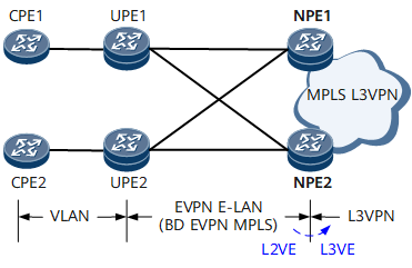
On the network shown in Figure 1, the first layer is the user-side access network where Layer 2 services are carried between CPEs and UPEs to implement VLAN forwarding. The second layer is the aggregation network where services are carried using EVPN E-LAN and BD-based EVPN MPLS is deployed between UPEs and NPEs. The third layer is the core network where services are carried using MPLS L3VPN. In this case. NPEs must be deployed with EVPN E-LAN accessing L3VPN. Specifically, configure an L2VE sub-interface to access BD EVPN on an NPE and then configure an L3VE sub-interface to access L3VPN. In this manner, when the public network packets of EVPN E-LAN reach the L2VE sub-interface on the NPE, the corresponding tag is encapsulated into the packets based on the tag processing behavior configured on the L2VE sub-interface. After the packets are loopbacked to the L3VE interface, the corresponding L3VE sub-interface is matched based on the tag carried in the packets, and the packets are forwarded using the corresponding L3VPN instance.
Feature Deployment
Before deploying EVPN E-LAN accessing L3VPN, complete the following tasks on an NPE:
- Create an L2VE interface and an L3VE interface and bind them to the same VE-Group.
- Create an L2VE sub-interface and add it to the BD to which the EVPN instance bound.
- Create an L3VE sub-interface, specify the associated VLAN, set the VLAN encapsulation mode (configure the Tag), and bind it to the corresponding L3VPN instance.