BGP SR LSP
BGP Segment Routing (SR) uses BGP as the control-plane protocol to transmit SR information. BGP uses the prefix SID attribute to advertise Segment Routing global block (SRGB) and Label-Index information for unified SR label deployment, after which BGP SR LSPs can be established. BGP SR LSPs are essentially BGP LSPs and are created in a similar way. The data forwarding process using BGP SR LSPs is also similar to that using BGP LSPs. The main difference between BGP SR LSPs and BGP LSPs lies in the label distribution mode. BGP SR LSPs use the SR label distribution mode, in which a label value is allocated to a specified route in a fixed mode (Label-Index+SRGB). This mode is a static label configuration mode, whereas BGP LSPs use a dynamic label allocation mode.
BGP SR LSP Creation
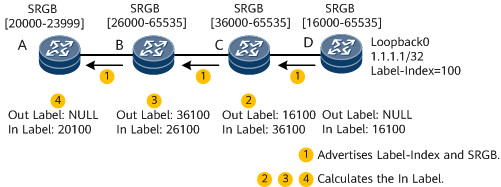
Table 1 describes the process of establishing a prefix SID-based BGP SR LSP.
Step |
Device |
Operation |
|---|---|---|
1 |
D |
An SRGB and Label-Index are configured on node D. The incoming label (In Label for short) of the route to 1.1.1.1/32 is 16100 on node D. In this case, node D instructs node C to use 16100 as the BGP SR LSP label for the route to 1.1.1.1/32. Node D creates an ILM entry to guide the processing of the In Label, encapsulates its SRGB and Label-Index into the Prefix SID attribute of a BGP route, and advertises the BGP route to its BGP peers. |
2 |
C |
After parsing the BGP message advertised by node D, node C sets the outgoing label (Out Label for short) to the In Label advertised by node D, instructs the tunnel management module to update the BGP LSP information, and delivers an NHLFE entry. In addition, node C calculates the In Label by adding the start value of its SRGB [36000–65535] and the Label-Index carried in the received message. The calculated In Label is 36100 (36000 + 100). After applying for the label, node C creates an ILM entry. |
3 |
B |
The process is similar to that on node C. The Out Label is 36100, and the In Label is 26100 (26000 + 100). |
4 |
A |
The process is similar to that on node B, and the In Label is 20100. |
Data Forwarding
BGP SR LSPs use the same three types of label operations as those used in MPLS: push, swap, and pop.
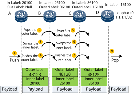
Table 2 describes the process of data forwarding on the network shown in Figure 2.
Step |
Device |
Operation |
|---|---|---|
1 |
A |
Node A receives a data packet and finds that the destination IP address of the packet is 1.1.1.1. Node A searches for the corresponding BGP LSP and pushes an inner MPLS label 20100 to the packet. Node A searches the inner and outer label mapping table, pushes an outer MPLS label 48123 to the packet, and forwards the packet through the outbound interface. NOTE:
To implement MPLS forwarding, each node creates an inner and outer label mapping table. Take node A as an example. According to the BGP SR LSP, when the inner label of a packet is 20100, the destination address is 1.1.1.1. According to the LDP LSP, when the packet needs to be sent to node B, the outer label 48123 needs to be added to the packet. Therefore, when the inner label of a packet is 20100, the outer label 48123 needs to be added. This mapping is recorded in the inner and outer label mapping table. With this table, node A does not need to query the IP routing table for an entry to send the packet to node B. Instead, node A only needs to query its inner and outer label mapping table for packet forwarding. |
2 |
B |
After receiving the labeled packet, node B searches for an LDP LSP and pops the outer label 48123. Then, node B searches for a BGP LSP and swaps the inner label from 20100 to 26100. Finally, node B queries its inner and outer label mapping table, pushes an outer label 48120 to the packet, and forwards the packet through the outbound interface. |
3 |
C |
The operations on node C are similar to those on node B. |
4 |
D |
After receiving the labeled packet, node D searches for an LDP LSP and pops the outer label 48125 from the packet. Then, node D searches for a BGP LSP, pops the inner label 36100 from the packet, and forwards the packet to the destination. |