iFIT Measurement Metrics
On a transit network with boundaries, flows enter and leave the network through some boundary devices. On the network shown in Figure 1, PIn is the number of packets entering the network in the ingress direction on Rn, and PEn is the number of packets leaving the network in the egress direction on Rn.
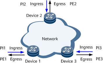
- The number of packets entering the network is the sum of all packets moving in the ingress direction: PI = PI1 + PI2 + PI3
- The number of packets leaving the network is the sum of all packets moving in the egress direction: PE = PE1 + PE2 + PE3
Delay is the difference between the time a service flow enters the network and the time the service flow leaves the network within a specified measurement interval.
Packet Loss Measurement
Packet loss measurement calculates the difference between the number of packets entering a transit network and the number of packets leaving the transit network within a measurement interval.
Figure 2 shows a typical network where end-to-end performance can be measured. Service packets enter the network through R1 and leave the network through R2.
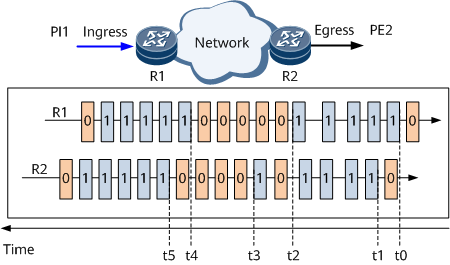
- t0: R1 sets the loss measurement flag to 1 for incoming service packets in the first interval and starts counting all service packets with the loss measurement flag of 1.
- t1: R2 starts receiving service packets with the loss measurement flag of 1 in the first interval and starts counting these service packets.
- t2: R1 finishes counting the incoming service packets with the loss measurement flag of 1 in the first interval and calculates the total number (PI1) of these service packets. R1 then sets the loss measurement flag to 0 for incoming service packets in the second interval and starts counting all service packets with the loss measurement flag of 0.
- t3: R2 finishes receiving service packets with the loss measurement flag of 1 in the first interval and calculates the total number (PE2) of these services packets.

At t1, R2 starts receiving service packets with the loss measurement flag of 1. At t3, after the internal timer has run for a specified interval, R2 determines that it has finished receiving service packets with the loss measurement flag of 1 in this interval. R2 determines this based on the elapsed interval rather than whether it has received service packets with the loss measurement flag of non-1. Therefore, out-of-order delivery does not affect service packet measurement. This mechanism ensures that service packet statistics in each interval are correctly collected.
- t4: R1 sets the loss measurement flag to 1 for incoming service packets in the third interval and starts counting all service packets with the loss measurement flag of 1.
- t5: R2 starts receiving service packets with the loss measurement flag of 1 in the third interval and starts counting these service packets.
R2 can obtain the number of received service packets with the loss measurement flag of 1 in the first interval any time between t3 and t5. The formula is LostPacket = PI1 – PE2.
If the peer end receives multiple copies of traffic during iFIT measurement, the result of the packet loss measurement is inaccurate.
Delay Measurement
Delay measurement calculates the period from when a service flow enters the network to when the service flow leaves the network over a specified interval.
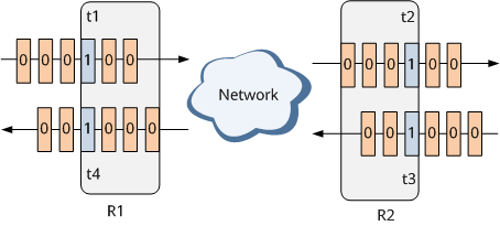
- When service packets are transmitted from R1 to R2, the procedure is as follows:
- t1: R1 sets the delay measurement flag to 1 for specified incoming service packets and obtains the timestamp t1.
- t2: R2 starts receiving the service packets with the delay measurement flag of 1 and obtains the timestamp t2.
- When service packets are transmitted from R2 to R1, the procedure is as follows:
- t3: R2 sets the delay measurement flag to 1 for specified incoming service packets and obtains the timestamp t3.
- t4: R1 starts receiving the service packets with the delay measurement flag of 1 and obtains the timestamp t4.
The one-way delay from R1 to R2 is: 1d (R1 -> R2) = t2 – t1. The one-way delay from R2 to R1 is: 1d (R2 -> R1) = t4 – t3. The two-way delay is: 2d = (t2 – t1) + (t4 – t3) = (t4 – t1) – (t3 – t2).