Example for Configuring Dynamic BGP VPN Flow Specification
In VPNs, if the characteristics of DoS or DDoS attack traffic is unknown, a traffic analysis server can help implement BGP VPN Flow Specification to ensure network security.
Networking Requirements
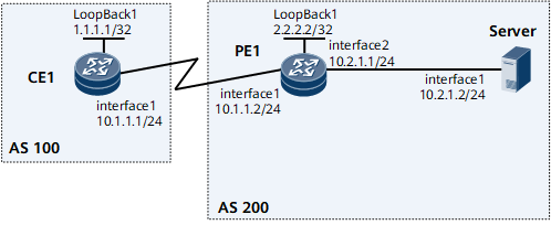
As shown in Figure 1, in a VPN, CE1 belongs to AS 100, while PE1 and Server belong to AS 200. PE1 is an ingress of AS 200. AS 200 communicates with AS 100 through PE1.
The attack source in AS 100 may flow into AS 200 through PE1, posing a threat to AS 200. In this situation, configure dynamic BGP VPN Flow Specification to ensure network security. The operation process is as follows: Deploy a traffic analysis server and establish a BGP VPN Flow Specification peer relationship between the traffic analysis server and PE1. PE1 samples traffic periodically and sends the sampled traffic to the traffic analysis server. The traffic analysis server generates a BGP VPN Flow Specification route based on the characteristics of sampled attack traffic and sends the route to PE1. PE1 converts the route into a traffic policy to filter and control attack traffic, ensuring the proper transition of services in AS 200.
Configuration Roadmap
The configuration roadmap is as follows:
Configure an IP address for each interface.
Create a VPN instance on PE1 and Server and bind the VPN instance to their interfaces.
Establish a BGP VPN Flow Specification peer relationship between PE1 and Server to enable the generated BGP VPN Flow Specification routes to be sent to PE1. Then a traffic policy is generated.

The traffic analysis server is a third-party device, and it must be a BGP VPN Flow Specification peer of another device.
Data Preparation
Router ID of CE1 (1.1.1.1) and router ID of PE1 (2.2.2.2)
AS number of CE1 (100) and AS number of PE1, and Server (200)
Name of a VPN instance (vpna)
Procedure
- Configure an IP address for each interface.
For detailed configurations, see the configuration files in this example.
- Create a VPN instance and bind it to each interface.
# Configure PE1.
[~PE1] ip vpn-instance vpna
[*PE1-vpn-instance-vpna] ipv4-family
[*PE1-vpn-instance-vpna-af-ipv4] route-distinguisher 100:1
[*PE1-vpn-instance-vpna-af-ipv4] vpn-target 111:1 export-extcommunity
[*PE1-vpn-instance-vpna-af-ipv4] vpn-target 111:1 import-extcommunity
[*PE1-vpn-instance-vpna-af-ipv4] commit
[~PE1-vpn-instance-vpna-af-ipv4] quit
[~PE1-vpn-instance-vpna] quit
[~PE1] interface GigabitEthernet0/1/0
[~PE1-GigabitEthernet0/1/0] undo shutdown
[*PE1-GigabitEthernet0/1/0] ip binding vpn-instance vpna
[*PE1-GigabitEthernet0/1/0] ip address 10.1.1.2 255.255.255.0
[*PE1-GigabitEthernet0/1/0] commit
[~PE1-GigabitEthernet0/1/0] quit
[~PE1] interface GigabitEthernet0/1/8
[~PE1-GigabitEthernet0/1/8] undo shutdown
[*PE1-GigabitEthernet0/1/8] ip binding vpn-instance vpna
[*PE1-GigabitEthernet0/1/8] ip address 10.2.1.1 255.255.255.0
[*PE1-GigabitEthernet0/1/8] commit
[~PE1-GigabitEthernet0/1/8] quit
- Configure a BGP VPN Flow Specification peer and disable route authentication.
# Configure PE1.
[~PE1]bgp 200
[*PE1-bgp] router-id 2.2.2.2
[*PE1-bgp] commit
[~PE1-bgp] vpn-instance vpna
[*PE1-bgp-instance-vpna] peer 10.1.1.1 as-number 100
[*PE1-bgp-instance-vpna] peer 10.2.1.2 as-number 200
[*PE1-bgp-instance-vpna] quit
[*PE1-bgp] ipv4-flow vpn-instance vpna
[*PE1-bgp-flow-vpna] peer 10.1.1.1 enable
[*PE1-bgp-flow-vpna] peer 10.2.1.2 enable
[*PE1-bgp-flow-vpna] peer 10.1.1.1 validation-disable
[*PE1-bgp-flow-vpna] peer 10.2.1.2 validation-disable
[*PE1-bgp-flow-vpna] commit
[~PE1-bgp-flow-vpna] quit
[~PE1-bgp] quit
- Verify the configuration.
# Check whether BGP VPN Flow Specification peer relationships are established on PE1. The command output shows that BGP VPN Flow Specification peer relationships are established.
<PE1> display bgp flow vpnv4 vpn-instance vpna peer

 BGP local router ID : 2.2.2.2
 Local AS number : 200

 VPN-Instance vpna, Router ID 2.2.2.2:
 Total number of peers : 2                 Peers in established state : 2

  Peer            V          AS  MsgRcvd  MsgSent  OutQ  Up/Down       State  PrefRcv
  10.1.1.1        4         100        3        5     0 00:00:06 Established        0
  10.2.1.2        4         200     9523     9530     0 0138h31m Established        1
# Check information about the BGP VPN Flow Specification routes received by PE1.
<PE1> display bgp flow vpnv4 vpn-instance vpna routing-table
 Total Number of Routes: 1
 * >  ReIndex : 2
      Dissemination Rules:
       Protocol       : eq 6
       Src. Port      : eq 159
       ICMP Code      : eq 3
       FragmentType   : match (Don't fragment)
       MED      : 0                   PrefVal  : 0
       LocalPref: 100
       Path/Ogn :  i
# Check the traffic filtering rule carried in the BGP VPN Flow Specification route by specifying ReIndex of the route.
<PE1> display bgp flow vpnv4 vpn-instance vpna routing-table 2
 ReIndex : 2
 Order   : 0
 Dissemination Rules :
   Protocol       : eq 6
   Src. Port      : eq 159
   ICMP Code      : eq 3
   FragmentType   : match (Don't fragment)

 BGP flow-ipv4 routing table entry information of 2:
 Match action :
   apply deny
 From: 10.2.1.2 (3.3.3.3)
 Route Duration: 0d00h04m37s
 AS-path Nil, origin igp, MED 0, localpref 100, pref-val 0, valid, internal, best, pre 255
 Advertised to such 1 peers:
    10.1.1.1
Configuration Files
CE1 configuration file
#
sysname CE1
#
interface GigabitEthernet0/1/0
 undo shutdown
 ip address 10.1.1.1 255.255.255.0
#
interface LoopBack1
 ip address 1.1.1.1 255.255.255.255
#
bgp 100
 router-id 1.1.1.1
 peer 10.1.1.2 as-number 200
 #
 ipv4-family unicast
  undo synchronization
  peer 10.1.1.2 enable
 #
 ipv4-family flow
  peer 10.1.1.2 enable
#
return
PE1 configuration file
#
sysname PE1
#
ip vpn-instance vpna
 ipv4-family
  route-distinguisher 100:1
  apply-label per-instance
  vpn-target 111:1 export-extcommunity
  vpn-target 111:1 import-extcommunity
#
interface GigabitEthernet0/1/0
 undo shutdown
 ip binding vpn-instance vpna
 ip address 10.1.1.2 255.255.255.0
#
interface GigabitEthernet0/1/8
 undo shutdown
 ip binding vpn-instance vpna
 ip address 10.2.1.1 255.255.255.0
#
interface LoopBack1
 ip address 2.2.2.2 255.255.255.255
#
bgp 200
 router-id 2.2.2.2
 #
 ipv4-family unicast
  undo synchronization
 #
 vpn-instance vpna
  peer 10.1.1.1 as-number 100
  peer 10.2.1.2 as-number 200
 #
 ipv4-flow vpn-instance vpna
  peer 10.1.1.1 enable
  peer 10.2.1.2 enable
#
return