Configuring an Out-of-Band GMPLS UNI Tunnel
This section describes how to establish a GMPLS UNI tunnel using an out-of-band control channel to connect an IP network to an optical network.
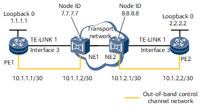
Networking Requirements
In Figure 1, PE1 and PE2 are IP devices, and NE1 and NE2 are optical transport devices. A customer wants to establish a GMPLS UNI tunnel to connect the IP network to the optical network. Since devices have sufficient interfaces, an out-of-bound control channel can be used to establish a GMPLS UNI tunnel.

Device Name |
Interface Name |
IP Address and Mask |
|---|---|---|
PE1 |
Loopback 0 |
1.1.1.1/32 |
GE 0/1/16 |
- This interface is a link interface of the TE-link and does not need to be assigned an IP address. |
|
GMPLS-UNI 1 |
10.2.1.1/30 |
|
GE 0/1/17 |
10.1.1.1/30 |
|
NE1 |
Node ID |
7.7.7.7/32 |
Port 0 |
10.1.1.2/30 |
|
PE2 |
Loopback 0 |
2.2.2.2/32 |
GE 0/1/16 |
- This interface is a link interface of the TE-link and does not need to be assigned an IP address. |
|
GE 0/1/17 |
10.1.2.2/30 |
|
GMPLS-UNI 1 |
10.2.1.2/30 |
|
NE2 |
Node ID |
8.8.8.8/32 |
Port 0 |
10.1.2.1/30 |
Configuration Notes
Configurations on the ingress and the egress of the GMPLS UNI tunnel are different.
In this example, configurations only of IP devices (PE1 and PE2) are described. For configuration details about optical devices, see the configuration guide for a specific optical device.
Configuration Roadmap
The configuration roadmap is as follows:
- Configure loopback interfaces and a GMPLS UNI service interface and assign IP addresses to the interfaces.
- Enable MPLS, MPLS TE, and MPLS RSVP-TE globally.
- Configure LMP, a TE-link, and a data-link.
- Configure an out-of-band control channel.
- Configure an explicit path.
Configure a GMPLS UNI tunnel along the path PE1 -> PE2 to connect the IP network to the transport network.
Data Preparation
To complete the configuration, you need the following data:
Device Name |
Parameter |
Value |
|---|---|---|
PE1 |
Number of a GMPLS UNI service interface |
1 |
Name of a GMPLS UNI tunnel |
toPE2 |
|
Tunnel ID |
1 |
|
Data switching type |
dcsc |
|
LMP peer |
ne1 |
|
TE-link |
Number: 1 Local interface ID: 192.168.1.1 Remote interface ID: 192.168.1.2 |
|
Explicit path |
Name: unipath Hops:
|
|
PE2 |
Number of a GMPLS UNI service interface |
1 |
Name of a GMPLS UNI tunnel |
toPE1 |
|
LMP peer |
ne2 |
|
TE-link |
Number: 1 Local interface ID: 192.168.2.2 Remote interface ID: 192.168.2.1 |
Procedure
- Configure loopback interfaces and a GMPLS UNI service interface and assign IP addresses to the interfaces.
# Configure PE1.
<PE1> system-view
[~PE1] interface LoopBack 0
[~PE1-LoopBack0] ip address 1.1.1.1 32
[*PE1-LoopBack0] quit
[*PE1] interface Gmpls-Uni 1
[*PE1-Gmpls-Uni1] ip address 10.2.1.1 255.255.255.252
[*PE1-Gmpls-Uni1] quit
[*PE1] commit
# Configure PE2.
<PE2> system-view
[~PE2] interface LoopBack 0
[~PE2-LoopBack0] ip address 2.2.2.2 32
[*PE2-LoopBack0] quit
[*PE2] interface Gmpls-Uni 1
[*PE2-Gmpls-Uni1] ip address 10.2.1.2 255.255.255.252
[*PE2-Gmpls-Uni1] quit
[*PE2] commit
- Enable MPLS, MPLS TE, and MPLS RSVP-TE globally.
# Configure PE1.
[~PE1] mpls lsr-id 1.1.1.1
[*PE1] mpls
[*PE1-mpls] mpls te
[*PE1-mpls] mpls rsvp-te
[*PE1-mpls] commit
[~PE1-mpls] quit
# Configure PE2.
[~PE2] mpls lsr-id 2.2.2.2
[*PE2] mpls
[*PE2-mpls] mpls te
[*PE2-mpls] mpls rsvp-te
[*PE2-mpls] commit
[~PE2-mpls] quit
- Configure LMP, a TE-link, and a data-link.
# Configure PE1.
[~PE1] lmp
[*PE1-lmp] peer ne1
[*PE1-lmp-peer-ne1] lmp static
[*PE1-lmp-peer-ne1] node-id 7.7.7.7
[*PE1-lmp-peer-ne1] te-link 1
[*PE1-lmp-peer-ne1-te-link-1] link-id local ip 192.168.1.1
[*PE1-lmp-peer-ne1-te-link-1] link-id remote ip 192.168.1.2
[*PE1-lmp-peer-ne1-te-link-1] data-link interface GigabitEthernet0/1/16 local interface-id 192.168.1.1 remote interface-id 192.168.1.2
[*PE1-lmp-peer-ne1-te-link-1] commit
[~PE1-lmp-peer-ne1-te-link-1] quit
[~PE1-lmp-peer-ne1] quit
[~PE1-lmp] quit
# Configure PE2.
[~PE2] lmp
[*PE2-lmp] peer ne2
[*PE2-lmp-peer-ne2] lmp static
[*PE2-lmp-peer-ne2] node-id 8.8.8.8
[*PE2-lmp-peer-ne2] te-link 1
[*PE2-lmp-peer-ne2-te-link-1] link-id local ip 192.168.2.2
[*PE2-lmp-peer-ne2-te-link-1] link-id remote ip 192.168.2.1
[*PE2-lmp-peer-ne2-te-link-1] data-link interface GigabitEthernet0/1/16 local interface-id 192.168.2.2 remote interface-id 192.168.2.1
[*PE2-lmp-peer-ne2-te-link-1] commit
[~PE2-lmp-peer-ne2-te-link-1] quit
[~PE2-lmp-peer-ne2] quit
[~PE2-lmp] quit
- Configure an out-of-band control channel.
# Configure PE1.
[~PE1] ip route-static 7.7.7.7 32 10.1.1.2
[*PE1] commit
# Configure PE2.
[~PE2] ip route-static 8.8.8.8 32 10.1.2.1
[*PE2] commit
- Configure an explicit path.
# Configure the explicit path on the ingress EN (PE1). The explicit path must be a strict four-hop path connecting ingress EN, ingress CN, egress CN, and egress EN.
# Configure PE1.
[~PE1] explicit-path unipath
[*PE1-explicit-path-unipath] next hop 192.168.1.1
[*PE1-explicit-path-unipath] next hop 192.168.1.2
[*PE1-explicit-path-unipath] next hop 192.168.2.1
[*PE1-explicit-path-unipath] next hop 192.168.2.2
[*PE1-explicit-path-unipath] commit
[~PE1-explicit-path-unipath] quit
- Configure forward and backward GMPLS UNI tunnels.
# Configure PE1.
[~PE1] gmpls-tunnel PE2
[*PE1-gmpls-tunnel-PE2] bind interface Gmpls-Uni1
[*PE1-gmpls-tunnel-PE2] destination 2.2.2.2
[*PE1-gmpls-tunnel-PE2] explicit-path unipath
[*PE1-gmpls-tunnel-PE2] bandwidth 100000
[*PE1-gmpls-tunnel-PE2] tunnel-id 1
[*PE1-gmpls-tunnel-PE2] switch-type dcsc
[*PE1-gmpls-tunnel-PE2] commit
[~PE1-gmpls-tunnel-PE2] quit
# Configure PE2.
<PE2> system-view
[~PE2] gmpls-tunnel toPE1
[*PE2-gmpls-tunnel-toPE1] passive
[*PE2-gmpls-tunnel-toPE1]  match-tunnel ingress-lsr-id 1.1.1.1 tunnel-id 1
[*PE2-gmpls-tunnel-toPE1] bind interface Gmpls-Uni1
[*PE2-gmpls-tunnel-toPE1] commit
[~PE2-gmpls-tunnel-toPE1] quit
- Verify the configuration.
After completing the preceding configuration, run the display mpls te gmpls tunnel-interface command to view the status of the GMPLS UNI tunnel and the protocol status of the service interface bound to the GMPLS UNI tunnel.
[~PE1] display mpls te gmpls tunnel-interface
    Tunnel Name       : toD
    Tunnel State Desc : CR-LSP is Up
    Session ID          : 1                     FTid         : 33
    Ingress LSR ID      : 1.1.1.1               Egress LSR ID: 2.2.2.2
    Admin State         : UP                    Oper State   : UP
    Signaling Protocol  : RSVP
    Bandwidth(Kbit/sec) : 1000
    Match Session ID    : -
    Passive             : NO
    Link Protect Type   : REROUTE               LSP Encoding Type : ETHERNET
    Switch Type         : DCSC                  Graceful Deleting : NO
    Bind Interface      : Gmpls-Uni1
    Authentication      : Disabled

    Primary LSP ID      : 1.1.1.1:43
    LSP State           : UP
    Resv Style          : SE              Bandwidth(Kbit/sec)   : 100000
    Explicit Path Name  : unipath
# After the tunnel goes Up, initiate a ping to the IP address of the service interface bound to the tunnel. The ping is successful, which indicates that the IP and optical networks have been successfully connected.[~PE1] ping 10.2.1.2 PING 10.2.1.2: 56 data bytes, press CTRL_C to break Reply from 10.2.1.2: bytes=56 Sequence=1 ttl=255 time=6 ms Reply from 10.2.1.2: bytes=56 Sequence=2 ttl=255 time=2 ms Reply from 10.2.1.2: bytes=56 Sequence=3 ttl=255 time=1 ms Reply from 10.2.1.2: bytes=56 Sequence=4 ttl=255 time=3 ms Reply from 10.2.1.2: bytes=56 Sequence=5 ttl=255 time=2 ms --- 10.2.1.2 ping statistics --- 5 packet(s) transmitted 5 packet(s) received 0.00% packet loss round-trip min/avg/max = 1/2/6 ms
Configuration Files
PE1 configuration file
#
sysname PE1
#
mpls lsr-id 1.1.1.1
#
mpls
 mpls te
 mpls rsvp-te
 mpls te cspf
#
explicit-path unipath
 next hop 192.168.1.1
 next hop 192.168.1.2
 next hop 192.168.2.1
 next hop 192.168.2.2
#
interface GigabitEthernet0/1/16
 undo shutdown
#
interface GigabitEthernet0/1/17
 undo shutdown
 ip address 10.1.1.1 255.255.255.252
#
interface LoopBack0
 ip address 1.1.1.1 255.255.255.255
#
interface Gmpls-Uni1
 undo shutdown
 ip address 10.2.1.1 255.255.255.252
#
lmp
 peer ne1
  lmp static
  node-id 7.7.7.7
  te-link 1
   link-id local ip 192.168.1.1
   link-id remote ip 192.168.1.2
   data-link interface GigabitEthernet0/1/16 local interface-id 192.168.1.1 remote interface-id 192.168.1.2
#
ip route-static 7.7.7.7 255.255.255.255 10.1.1.2
#
gmpls-tunnel gmpls-tunnel toPE2
 destination 2.2.2.2
 bind interface Gmpls-Uni1
 switch-type dcsc
 bandwidth 1000
 explicit-path unipath
 tunnel-id 1
#
return
PE2 configuration file
#
sysname PE2
#
mpls lsr-id 2.2.2.2
#
mpls
 mpls te
 mpls rsvp-te
 mpls te cspf
#
interface GigabitEthernet0/1/16
 undo shutdown
#
interface GigabitEthernet0/1/17
 undo shutdown
 ip address 10.1.2.2 255.255.255.252
#
interface LoopBack0
 ip address 2.2.2.2 255.255.255.255
#
interface Gmpls-Uni1
 undo shutdown
 ip address 10.2.1.2 255.255.255.252
#
lmp
 peer ne2
  lmp static
  node-id 8.8.8.8
  te-link 1
   link-id local ip 192.168.2.2
   link-id remote ip 192.168.2.1
   data-link interface GigabitEthernet0/1/16 local interface-id 192.168.2.2 remote interface-id 192.168.2.1
#
ip route-static 8.8.8.8 255.255.255.255 10.1.2.1
#
gmpls-tunnel toPE1
 passive
 bind interface Gmpls-Uni1
 match-tunnel ingress-lsr-id 1.1.1.1 tunnel-id 1
#
return