Configuring Routes for the Tunnel
Routes for a tunnel must be available on both the source and destination devices so that packets encapsulated with GRE can be forwarded correctly. A route passing through tunnel interfaces can be a static route or a dynamic route.
Context
A static route must be configured on both the source and destination devices if it is to be configured. The destination address of the route is the destination address of the packet that is not encapsulated by GRE, rather than the destination address of the tunnel or the peer tunnel interface address. The outbound interface is the local tunnel interface.
- When configuring a dynamic routing protocol, enable the protocol on both the tunnel interface and the physical interface connected to the private network. When you configure a route to the remote end of a tunnel, the next hop cannot be the address of the tunnel interface. Otherwise, GRE encapsulated packets cannot be forwarded properly.
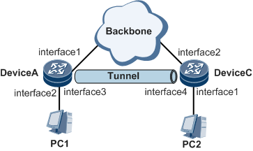
As shown in Figure 1, the source interface of Tunnel1 is interface1 on DeviceA, and the destination physical interface of Tunnel1 is interface2 on DeviceC. When configuring a dynamic routing protocol, you need to enable the protocol on both the tunnel interface and the interface connected to the PC. In the routing table, the outbound interface for the route to interface2 on DeviceC cannot be Tunnel1.
In practical configurations, different routing protocols or different processes of the same routing protocol need to be used for tunnel interfaces and public network physical interfaces. This prevents a tunnel interface from being selected as an outbound interface of routes to the destination of the tunnel. In addition, this also ensures that users packets are forwarded through the tunnel instead of the physical interface.

Perform the following steps on the devices at two ends of a tunnel.
Procedure
- Run system-view
The system view is displayed.
- Choose one of the following methods to configure routes passing through the tunnel interface.
Run the ip route-static ip-address { mask | mask-length } tunnel interface-number [ description text ] command to configure a static route.
Configure dynamic routes using IGP or BGP. Details for the procedure are not provided here. For the configuration of dynamic routes, see the NetEngine 8000 F Configuration Guide - IP Routing.
- Run commit
The configuration is committed.